- 17 -
6.6
RS485
CONNECTION
The
HD35APS
base unit version has a RS485 communication port with
MODBUS-RTU
proto-
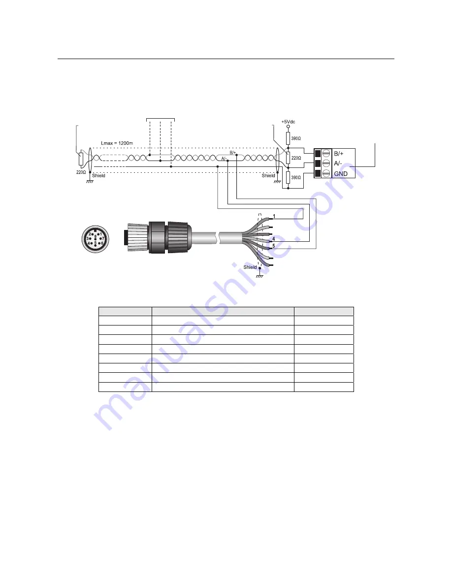
col. For connection to the port, use the CPM12-8P… series cables with 8-pole M12 connector.
The figure and the table below show the numbering and the function of the connector con-
tacts:
Fig. 6.6.1: RS485 connection
TAB. 6.6.1: CPM12-8P… cable
Connector
Function
Color B
1 GND Black
2 Not
connected
3 Not
connected
4 RS485
A/-
Brown
5 RS485
B/+
White
6 Not
connected
7 Not
connected
8 Not
connected
Thanks to RS485 connection, several instruments can be connected in a multi-point network.
The instruments are connected in sequence by means of a shielded cable with twisted pair
wires for signals and a third wire for the ground.
Line terminations must be placed at the ends of the network. In order for the line to be polarized
during non-transmission periods, resistors are used to connect signal lines and power supply.
Polarization resistors are in one point only in the line, in the proximity of the PC or PLC. The ca-
ble shield must be connected to both ends of the line.
The maximum number of devices that can be connected to the line (Bus) RS485 depends on the
load characteristics of the devices to be connected. The RS485 standard requires that the total
load doesn’t exceed 32 (Unit Loads). The load of a base unit HD35APS is equal to 1 unit load. If
the total load is higher than 32 unit loads, divide the network in segments and add a signal re-
peater between a segment and the following. A line termination must be placed at both ends of
each segment.
The cable maximum length depends on the transmission speed and on the cable characteris-
tics. Typically, the maximum length is 1200
m. The data line must be kept separated from any
power lines to avoid interferences to the transmitted signal.
White
Brown
Black
CPM12-8P…cable
M12 male
connector
of base unit
PLC or
RS485/USB or RS485/RS232
converter for PC
Other sensors with
RS485 output
Termination
Termination


