background image

-   43   - 

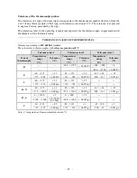
Tolerance of the thermocouple probes: 


The tolerance of a type of thermocouple corresponds to the maximum acceptable deviation from the 
e.m.f. of any thermocouple of that type, with reference junction at 0°C. The tolerance is expressed 
in degrees Celsius, preceded by the sign.


The tolerances refer to the operating temperature expected for the thermocouple, in agreement with 
the diameter of the thermoelements.


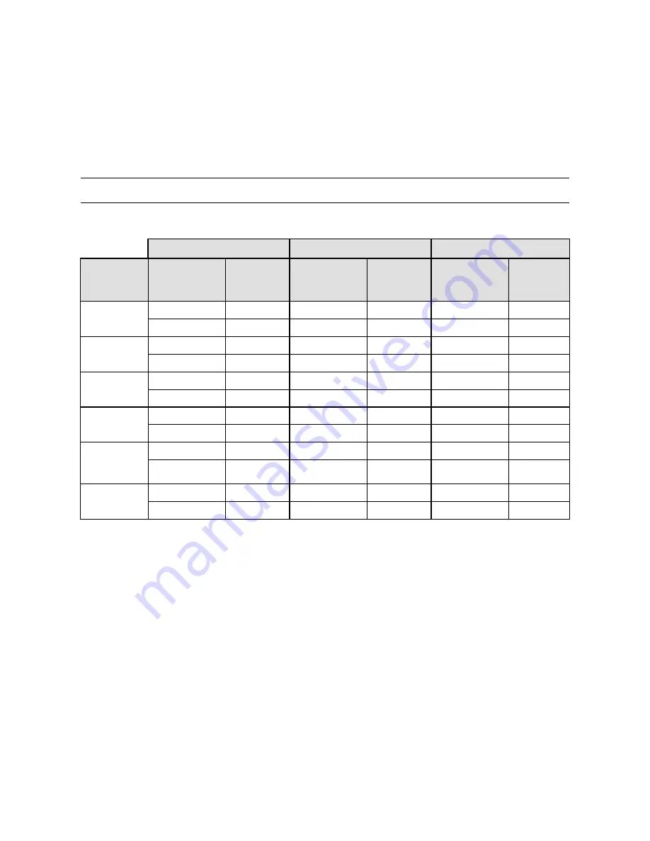
TOLERANCE CLASSES OF THERMOCOUPLES 

Tolerances according to 

IEC 60584-2

 standard.  

The values refer to thermocouples with 

reference junction at 0 °C

.  


Tolerance class 1 

Tolerance class 2 

Tolerance class 3 

Type of 

thermocouple 

Temperature 

range 

(°C) 

Tolerance

(°C) 

Temperature

range 

(°C) 

Tolerance

(°C) 

Temperature 

range 

(°C) 

Tolerance

(°C) 

--- --- 

+600…+1700 

± 0.0025 

 t 

+600…+800  

± 4 

--- --- --- --- 

+800…+1700 


± 0.005 

 t 

-40…+375  

± 1.5 

-40…+333  

± 2.5 

-167…+40  

± 2.5 

+375…+800  

± 0.004 

 t 

+333…+900  

± 0.0075 

 t 

-200…-167  

± 0.015 

 t 

-40…+375  

± 1.5 

-40…+333  

± 2.5 

--- 

--- 

+375…+750  

± 0.004 

 t 

+333…+750  

± 0.0075 

 t 

--- --- 

K , N 

-40…+375  

± 1.5 

-40…+333  

± 2.5 

-167…+40  

± 2.5 

+375…+1000   ± 0.004 

 t 

+333…+1200  ± 0.0075 

 t 

-200…-167  

± 0.015 

 t 

R , S 

0…+1100  

± 1 

0…+600  

± 1.5 

--- 

--- 

+1100…+1600  

± [1+0.003 

(t-1100)] 

+600…+1600  ± 0.0025 

 t 

--- --- 

-40…+125  

± 0.5 

-40…+133  

± 1 

-67…+40  

± 1 

+125…+350  

± 0.004 

 t 

+133…+350  

± 0.0075 

 t 

-200…-67  

± 0.015 

 t 

Note: t = temperature of measurement junction in °C. 


Summary of Contents for HD32.8.16

Page 1: ... manual and the instrument that you have purchased We cannot entirely exclude errors in the manual for which we apologize The data figures and descriptions contained in this manual cannot be legally asserted We reserve the right to make changes and corrections without prior notice HD32 8 8 HD32 8 16 Datalogger for thermocouples ENGLISH REV 1 2 12 12 2016 ...

Page 2: ... 2 HD32 8 8 Datalogger for 8 Thermocouples HD32 8 16 Datalogger for 16 Thermocouples ...

Page 3: ...elect the type of thermocouple using the arrows Using the arrows you can display the inputs in groups of four the probes from C1 to D4 are present in the HD32 8 16 model 9 PRINT key It starts and ends the data transfer to the serial USB communication port 10 MEM key It starts and ends the recording of the data 11 SETUP key It allows to enter and exit the instrument s functioning parameter setting ...

Page 4: ... Manager 19 4 3 Serial Menu Serial Communication 22 4 3 1 The Baud Rate 23 4 3 2 Print Interval 23 4 4 Reset 24 4 5 Contrast 24 4 6 Firmware 25 4 7 Time date 25 4 8 Calibrate 26 4 9 Key lock 26 4 10 Password 27 5 PROBES AND MEASUREMENTS 29 5 1 Temperature Measurement 29 5 2 Warnings care and maintenance of the probes 30 6 INSTRUMENT SIGNALS AND FAULTS 31 7 BATTERY SYMBOL AND BATTERY REPLACEMENT MA...

Page 5: ... 5 11 1 Connection to the RS232C serial port 39 11 2 Connection to the USB 2 0 port 39 12 FUNCTIONING NOTES AND OPERATING SAFETY 40 13 TECHNICAL CHARACTERISTICS 41 14 ORDERING CODES 44 ...

Page 6: ...0 and later Through the RS232 serial port you can transfer the data in real time to an 80 column serial printer NOTE The set capture and print intervals are valid for all the probes Other user selectable settable parameters are The units of measurement for the displayed temperature quantities C F K The system date and time The display of the maximum minimum and average statistic parameters The rel...

Page 7: ...cted and the unused inputs The probes are displayed in groups of four according to the order of the connectors from left to right From input A1 to input B4 in the HD32 8 8 model and from input A1 to input D4 in the HD32 8 16 model The unused inputs are not shown in the list If you have more than four probes connected at the same time use the arrows to move from one group to the other If a probe is...

Page 8: ...The keys on the instrument perform the following functions ON OFF key It turns the instrument on and off When turning on the instrument using this key the first screen will be displayed After few seconds the temperatures measured by the connected probes will be displayed NOTE The display shows only the inputs to which the probes are connected The probes are detected during turn on If a probe is la...

Page 9: ...s They activate the function in the lower line of the display indicated by the arrow in the figure the function enabled by SHIFT FNC is selected and displayed in reverse e g in the figure the C function is enabled SETUP key It allows to enter and exit the instrument s functioning parameter setting menu ENTER key In the menu it confirms the entered data ESC key It allows to exit from the menu or in...

Page 10: ...nting of the data via the serial port the data printing interval must be set in the menu Arrow keys Allow navigation through the menus selection of the type of thermocouple and choice of the inputs to be displayed During measurement you can select the type of thermocouple using the arrows The connected thermocouples screens are display with the arrows ...

Page 11: ...ailable inputs are arranged in groups of four probes each A B C and D A1 is the first input of group A A2 the second input and so on until input B4 for the HD32 8 8 and input D4 for the HD32 8 16 Use the F1 F2 and F3 keys to select the unit of measurement C F or K 3 1 THE UNIT OF MEASUREMENT UNIT By using the Functions menu enabled by the SHIFT FNC key select the unit of measurement for the temper...

Page 12: ... the Functions menu you can also display the relative value of the measured temperatures This function clears the current temperature measurement and displays for all inputs the difference between the current value and that measured when the function was activated 1 Use SHIFT FNC to open the drop down menu 2 Use the arrows to select rel 3 Press ENTER to confirm the rel message is displayed in the ...

Page 13: ...urn off during logging between one capture and the next The function is controlled by the Self_shut_off_Mode menu parameter When the logging interval is less than one minute the logging instrument remains on with an interval of at least one minute it turns off between one capture and the next if the Self_shut_off_Mode parameter is enabled For the details see par 4 2 MENU LOGGING ...

Page 14: ...urn to the previous menu press ESC To exit the menu and return directly to measurement press SETUP 4 1 INFO MENU To access the Info menu open the main menu using the SETUP key Using the arrows select Info and confirm with ENTER The following information on the instrument will be displayed Instrument code firmware date and version serial number instrument calibration date user identification code T...

Page 15: ... Interval 1 Use the arrows to select the interval duration from a minimum of 2 seconds to a maximum of one hour 2 Press ENTER to confirm and return to the Logging menu 3 Press ESC to return to the Logging menu without making any change 4 Press ESC again to return to the main menu 5 Press SETUP to exit immediately from the menu These are the available values 2 5 10 15 30 seconds 1 2 5 10 15 20 30 m...

Page 16: ...turn to the main menu 4 Press SETUP to exit immediately from the menu 4 2 3 Start stop time The logging start and end date and time can be programmed When called the function suggests the current time plus 5 minutes as the start time Press ENTER to confirm or set the date and time using the arrows Then you are asked to set the data to end the recording By default factory setting the instrument sug...

Page 17: ...ime enter stop time window will be displayed 1 Press ENTER to confirm the data prompted by the instrument 2 To change the prompted data use the arrows to select the data to be changed year month day and hour minutes seconds 3 The selected data will flash 4 Use the arrows to change its value 5 Confirm by pressing ENTER 6 Press ESC to return to the Logging menu without making any change 7 Press ESC ...

Page 18: ...ted the instrument is turned on few seconds before the start time and if powered by the mains it remains on at the end of logging If it is powered by the battery it is turned off when idle for some minutes at the end of the logging session NOTE 2 Use of the MEM key after setting the automatic start and stop If the automatic start and stop have been set and before the automatic start you press the ...

Page 19: ...ee the previous paragraph to set a new automatic start time after cancelling the previous one 4 2 5 Log File Manager This item allows managing the captured logging sessions The instrument allows printing the files of the captured sessions Print selected log cancelling the entire memory Erase ALL logs and selecting the memory management mode Select memory Type The instrument can store up to 64 LOG ...

Page 20: ...to the instrument RS232C serial port A parallel port printer requires a serial parallel converter between the instrument and the printer non supplied Before starting the printing via the RS232C port you have to set the baud rate To do so select the Baud Rate in the menu Serial see par 4 3 1 The Baud Rate and select the maximum value equal to 38400 baud To connect a printer use the maximum allowed ...

Page 21: ...e file 00 is selected The recording started at 18 50 on 27 January 2006 The file contains 6 samples 3 Press ENTER to print the selected log or press ESC to return to the previous menu without printing 4 The data transfer message will be displayed a few seconds then the instrument will go back to the Print selected log page to select another log to be printed 5 Repeat the procedure to print the req...

Page 22: ...L COMMUNICATION The Serial submenu allows setting the data transfer speed via the serial port Baud rate and the record printing interval Print Interval The LOG sessions can be downloaded on a PC through the serial RS232 or USB connection In case of serial connection the transfer speed can be set by the user see next par up to a maximum of 38400 baud In case of USB connection the transfer speed is ...

Page 23: ...rates are the same If the USB connection is used this parameter value is automatically set 4 3 2 Print Interval To set the Print Interval proceed as follows 1 Use the arrows to select the item 2 Press ENTER You will get the following message 3 Use the arrows to set the value 4 Press ENTER to confirm and return to the previous page or press ESC to cancel the change and exit the menu item 5 Press ES...

Page 24: ...elect Reset 3 Press ENTER You will get the following message 4 Use the arrows to select Reset 5 Press ENTER to confirm or ESC to exit the submenus without resetting the instrument 6 Press SETUP to exit immediately from the main menu 4 5 CONTRAST This menu item allows increasing or decreasing the contrast on the display To access the Contrast submenu proceed as follows 1 Press SETUP 2 Use the arrow...

Page 25: ...UP 2 Use the arrows to select Time date 3 Press ENTER 4 You will get the following message 5 Use the arrows to select the data to be set year month day and hour minutes 6 Once selected the data will start blinking 7 Use the arrows to enter the correct value 8 Press ENTER to confirm and return to the main menu 9 Or press ESC to return to the menu without making any change 10 Press SETUP to exit imm...

Page 26: ...m the main menu NOTE The calibration date cannot be modified by the user 4 9 KEY LOCK This menu item allows to lock unlock the instrument keyboard when the password has been input See the next chapter for further details To access the Key lock submenu proceed as follows 1 Press SETUP 2 Use the arrows to select Key lock 3 Press ENTER 4 You will get the following message Enter the password to lock t...

Page 27: ...wrong you will get the message Wrong password The default password is 0000 four zeroes 4 10 PASSWORD This menu item allows to set a password to protect the instrument from unauthorized access There are two types of available passwords both consisting of four characters The user password Can be set by the user to protect the instrument from unauthorized access The factory password Reserved to Techn...

Page 28: ...e the arrows to enter the new password 11 Press ENTER to confirm or ESC to cancel and return to the main menu 12 Press SETUP to exit immediately from the main menu WARNING Using the User password you can lock unlock the instrument see Paragraph 4 9 KEY LOCK ...

Page 29: ... measurements Adjustable height up to 1 50 meters complete with head that can host up to 6 measurement probes The same tripod can be used to support the measurement instrument during data capture The arms fitted with suitable clamps for the measurement probes can be inserted in the head code HD3218K The VTRAP32K kit is composed of a tripod code VTRAP32 and 5 arms code HD3218K The instrument is sup...

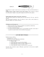
Page 30: ... them upward or downward Comply with the correct polarity of the probes Do not bend or force the contacts when inserting the probe connector into the instrument Do not bend deform or drop the probes as this could cause irreparable damage Always select the most suitable probe for your application To obtain reliable measurements temperature variations that are too rapid must be avoided The thermocou...

Page 31: ...g turn on is disconnected or faulty Over Overflow appears when the probe detects a higher value than expected measurement range for that type of thermocouple Under Underflow appears when the probe detects a lower value than expected measurement range for that type of thermocouple WARNING MEMORY FULL The instrument cannot store further data the memory space is full This appears only if the circular...

Page 32: ... symbol becomes when the external power supply is connected To replace the batteries proceed as follows 1 Switch the instrument off 2 Disconnect the external power supply if connected 3 Unscrew the battery cover screw counter clockwise and take out the battery holder Do not pull the battery connection wires as they could break 4 Replace the batteries 4 1 5V alkaline C BABY batteries Check that the...

Page 33: ...s should be removed when the instrument is not used for an extended time Flat batteries must be replaced immediately Avoid loss of liquid from batteries Use waterproof and good quality batteries if possible alkaline Sometimes on the market it is possible to find new batteries with an insufficient charge capacity 8 INSTRUMENT STORAGE Instrument storage conditions Temperature 25 65 C Humidity less t...

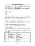
Page 34: ...ort is connected to a PC the RS232 serial port is automatically disabled and vice versa The instruments are provided with a complete set of commands and data queries to be sent via the PC All the commands transferred to the instrument must have the following structure XXCR where XX is the command code and CR is the Carriage Return ASCII 0D The XX command characters are exclusively upper case chara...

Page 35: ... is displayed if it is free a point is displayed P0 Ping locks the instrument keyboard for 70 seconds P1 Unlocks the instrument keyboard RA Sample log 30sec Reading of LOG interval set RL Sample print 0sec Reading of PRINT interval set S0 Printing of the current measurement of all inputs S1 Printing of the REL current measurement of all inputs WA Setting LOG interval is a hexadecimal number 1 D th...

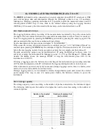
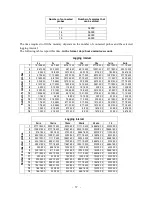
Page 36: ...e next logging instant it turns on again to capture the new sample and then turns off The data stored in the memory can be transferred to a PC using the DeltaLog9 software vers 3 0 and later or using the instrument File Manager see par 4 2 5 Log File Manager During data transfer the display shows the message DUMP to stop the data transfer press ESC on the instrument or on the PC If during a loggin...

Page 37: ...40 3 5 46 40 6 11 33 20 9 17 20 0 19 10 40 0 38 21 20 0 77 18 40 0 14 1 7 6 40 3 5 46 40 6 11 33 20 9 17 20 0 19 10 40 0 38 21 20 0 77 18 40 0 15 1 2 40 0 2 18 40 0 5 13 20 0 8 8 0 0 16 16 0 0 33 8 0 0 66 16 0 0 16 1 2 40 0 2 18 40 0 5 13 20 0 8 8 0 0 16 16 0 0 33 8 0 0 66 16 0 0 Logging interval 5min 10min 15min 20min 30min 1h Number of connected probes 1 2777 18 40 0 5555 13 20 0 8333 8 0 0 1111...

Page 38: ...er via a USB connector does not work Some keys are disabled during logging The following keys are enabled MEM SETUP TIME ENTER and ESC 10 2 THE PRINT FUNCTION Press PRINT to send the measured data directly to the RS232 ports in real time The printed data units of measurements are the same as those used on the display The function is started by pressing PRINT The time interval between two consecuti...

Page 39: ...ION TO THE RS232C SERIAL PORT 1 The measuring instrument has to be switched off 2 Using the null modem Delta Ohm 9CPRS232 cable connect the measurement instrument to the first free serial port COM of the PC 3 Turn on the instrument and set the baud rate to 38400 SETUP key Serial Baud Rate select 38400 using the arrows and confirm with ENTER The parameter remains in the memory 4 Launch the DeltaLog...

Page 40: ...nctioning and operating security can be ensured only within the climatic conditions specified in the chapter TECHNICAL CHARACTERISTICS Do not use or store the instrument in ways and or places in which there are Quick environment temperature changes that could cause condensation Corrosive or inflammable gases Direct vibrations or shocks against the instrument High intensity electromagnetic fields s...

Page 41: ...c 1A connector external 5 5mm internal 2 1mm Power supply via the PC USB port Autonomy 200 hours with 7800mAh alkaline batteries and all probes connected Power absorbed 6Vdc 60μA when the instrument is off 60μA in sleep mode with all probes connected 40mA during data capture with all probes connected Security of stored data Unlimited Connections Number of inputs 8 for the HD32 8 8 16 for the HD32 ...

Page 42: ...nth max deviation Unit of measurement C F K Keyboard 15 keys the instruments can also be configured without a PC Password and locking of the keyboard function Memory Divided in 64 blocks Storage capacity Up to 800 000 recordings divided amongst the existing inputs i e with one probe connected 800 000 recordings with 8 probes connected 96 000 recordings Logging interval Selectable among 2 5 10 15 3...

Page 43: ...ues refer to thermocouples with reference junction at 0 C Tolerance class 1 Tolerance class 2 Tolerance class 3 Type of thermocouple Temperature range C Tolerance C Temperature range C Tolerance C Temperature range C Tolerance C B 600 1700 0 0025 t 600 800 4 800 1700 0 005 t E 40 375 1 5 40 333 2 5 167 40 2 5 375 800 0 004 t 333 900 0 0075 t 200 167 0 015 t J 40 375 1 5 40 333 2 5 375 750 0 004 t ...

Page 44: ...management of the data on PC using Windows from 98 operating systems HD32 8 8 and HD32 8 16 probes It is possible to connect all the temperature probes with thermocouples type K J T N R S B and E using a male miniature connector Different probes can be supplied on request HD32 8 8 and HD32 8 16 accessories 9CPRS232 Connection cable with sub D 9 pole female connectors for RS232C null modem CP22 Con...

Page 45: ... 45 NOTES ...

Page 46: ... 46 NOTES ...

Page 47: ...roducts conform to following European Directives Direttive Directives 2014 30 EU Direttiva EMC EMC Directive 2014 35 EU Direttiva bassa tensione Low Voltage Directive 2011 65 EU RoHS RoHS Norme armonizzate applicate o riferimento a specifiche tecniche Applied harmonized standards or mentioned technical specifications Norme armonizzate Harmonized standards EN 61010 1 2010 Requisiti di sicurezza ele...

Page 48: ...hird parties is excluded from the guarantee The instrument shall be returned FREE OF SHIPMENT CHARGES to your dealer The jurisdiction of Padua applies in any dispute The electrical and electronic equipment marked with this symbol cannot be disposed of in public landfills According to the Directive 2011 65 EU the european users of electrical and electronic equipment can return it to the dealer or m...

Reviews: