HD35
- 36 -
V1.12
8
HD35ED… DATA LOGGERS FOR INDOOR USE
8.1
D
ESCRIPTION
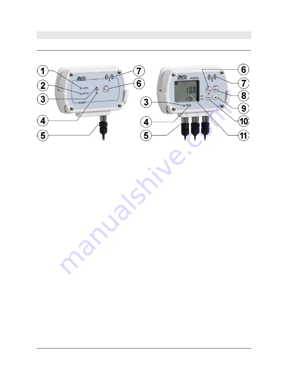
Models without LCD display
Models with LCD display
1.
ALARM LED: red color; it blinks when a measurement is in alarm condition.
2.
BATTERY LED: green color, it indicates the internal battery charge level. As the battery is
running low, the LED blinks with a lower frequency (the blinking period increases of 1 sec-
ond for each 10% decrease of the battery charge).
3.
Red RF LED: it blinks to signal that data transmission has failed.
4.
Green RF LED: it blinks when the data transmission has been successful.
5.
Probes and/or integrated sensors. The aspect of the lower part of the data logger depends
on the model (see the following page).
6.
Connection / PING (for testing RF) button.
7.
Internal RF antenna.
8.
MENU/ENTER key: allows access to the configuration menu; confirm the selected option or
the set value in the menu.
9.
key: in normal operation, it scrolls the quantities measured by the data logger; it scrolls
upwards the available options or decreases the set value in the menu.
10.
FUNC/
key: in normal operation, it displays the maximum (MAX), the minimum (MIN)
and the average (AVG) of the measurements; it scrolls downwards the available options or
decreases the set value in the menu.
11.
LCD Display. The type of display, custom or graphic, depends on the model.
The green and red RF LEDs blink simultaneously if the device is in error condition.
Note: some models of data loggers may be equipped with mini-USB connector, on the housing
side, whose use is reserved to the technical assistance.
Summary of Contents for HD35AP series
Page 120: ...HD35 120 V1 12 HD35EDLM TC...
Page 141: ...NOTES...
Page 142: ...NOTES...
Page 143: ...NOTES...


