HD35
- 54 -
V1.12
The input types 4-20mA and 4-20mA Mapped also work with 0-20 mA signals. The input types
Counter and Frequency are only in channel Ch 3.
Set NO MEASURE if the channel is not used.
The indication Mapped means that a linear correspondence between input values (in mA, mV,
V,
Ω
or counts) and the values of a physical quantity will be associated to the channel. For ex-
ample, if 4-20mA is selected, the data logger stores the input value in mA; if 4-20mA Mapped
is selected, the data logger doesn’t store the input value in mA but the corresponding value of
the physical quantity associated to the input.
By selecting a Mapped-type configuration, the guided procedure for the association between
the input values (in mA, mV, V,
Ω
or counts) and the values of the corresponding physical
quantity is started. The procedure is illustrated below:
1.
After confirming the selection of a Mapped input, the procedure start message is dis-
played, press ENTER to continue.
2.
Select the measurement unit of the physical quantity among those proposed by the in-
strument. If the desired measurement unit is not in the list, select NOT DEF (not defined).
Select the option OK and confirm with ENTER to continue.
3.
Select the measurement resolution of the physical quantity among those proposed by the
instrument. Select the option OK and confirm with ENTER to continue.
4.
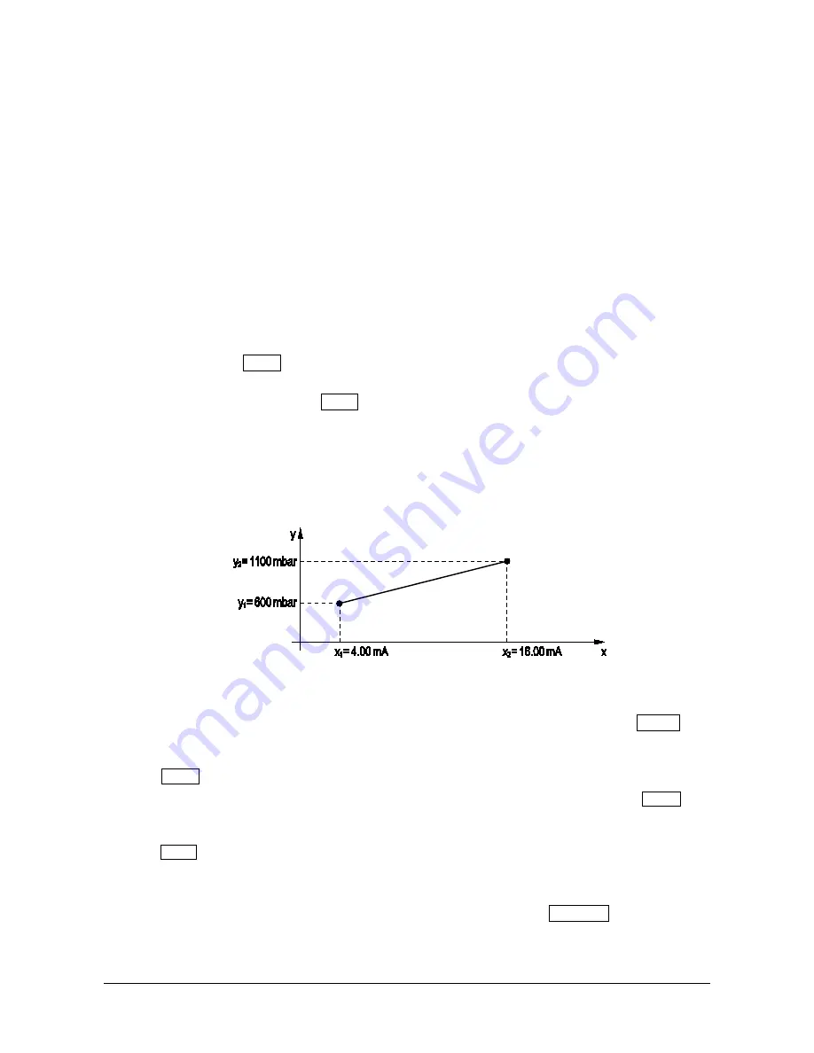
A message will be displayed reminding that the two coordinates of the linear relation be-
tween input and physical quantity will be now required:
x1=input value (in mA, mV, V,
Ω
or counts) in the first point,
y1=value of the physical quantity corresponding to the input value x1,
x2=input value (in mA, mV, V,
Ω
or counts) in the second point,
y2=value of the physical quantity corresponding to the input value x2,
Fig. 8.5.3: association of a physical quantity to the input signal
press ENTER to continue.
5.
Select the input value x1 for the first point (e.g. 4.00 mA). Select the option OK and
confirm with ENTER to continue.
6.
Select the physical quantity value y1 for the first point (e.g. 600 mbar). Select the op-
tion OK and confirm with ENTER to continue.
7.
Select the input value x2 for the second point (e.g. 20.00 mA). Select the option OK and
confirm with ENTER to continue.
8.
Select the physical quantity value y2 for the second point (e.g. 1100 mbar). Select the op-
tion OK and confirm with ENTER to continue.
9.
The message requesting confirmation of the configuration storage is displayed, press YES
to save the settings and terminate the procedure.
The procedure can be stopped at any moment by selecting the option CANCEL and confirming
with ENTER.
A user name can be associated to each measurement channel to remind the type of physical
quantity detected. The user name can be set only through the HD35AP-S software.
Physical quantity
(e.g. Atm. Pressure)
Input signal
(e.g. 4…20 mA)
Summary of Contents for HD35AP series
Page 120: ...HD35 120 V1 12 HD35EDLM TC...
Page 141: ...NOTES...
Page 142: ...NOTES...
Page 143: ...NOTES...


