HD35
- 9 -
V1.12
Note: even the base units HD35APW and HD35APR, with Wi-Fi and/or Ethernet interface, must
first be connected to the PC via USB through the CP31 cable for setting the parameters of the
local network (e.g., for setting the IP address, for choosing the Wi-Fi or Ethernet mode, etc.).
4.
C
ONNECT THE SOFTWARE TO THE BASE UNIT
Start the HD35AP-S software in your PC and perform the connection procedure illustrated in
the chapter " Connection to base unit " of the software online help.
5.
C
HECK THE CLOCK SETTING
Select the item " Setting of date and time " of HD35AP-S software and make sure that the
clock of the base unit is updated. If the clock is not updated, set it as explained in the chapter
" Clock setting " of the software online help.
6.
C
ONNECT THE BATTERY OF THE OTHER NETWORK DEVICES
Connect the battery of the other devices following the procedure indicated at step 2 of the pre-
vious page. In the devices with waterproof housing, the position of the battery and the con-
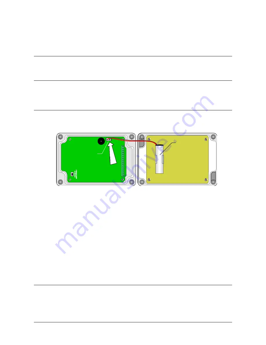
nector is shown in the following figure.
Fig. 3.4: battery in devices with waterproof housing
The models in waterproof housing with CO
2
probe and the model with RS485 Modbus-RTU in-
put have no internal battery: connect the 7…30 Vdc external power supply.
•
Factory-configured system: at startup, data loggers synchronize the clock with that of the
base unit. If the base unit is not yet connected to the power supply, the synchronization fails
and data loggers with LCD option display the clock setting window. Clock synchronization will
anyway take place automatically after connecting the base unit to the power supply. Mean-
while, data loggers start storing measurements with their date and time, not synchronized
with respect to the system measurements. If you wish to set the clock manually, see para-
graph The menu in LCD data loggers on page 44.
•
Not configured system: at startup, data loggers don’t synchronize the clock with that of
the base unit. In the data loggers with LCD, the window for the clock setting is displayed.
Clock synchronization will take place automatically after network configuration (step 8), in
the meantime data loggers start storing measurements with their date and time. If you wish
to set the clock manually, see paragraph The menu in LCD data loggers on page 44.
7.
A
CTIVATING THE
RF
STAGE IN THE DEVICES
(
DATA LOGGERS
,
REPEATERS AND ALARM MODULES
)
In the devices belonging to a factory-configured system, the RF stage is activated automatical-
ly. In this case, proceed to step 9.
If the system is not factory-configured, the RF stage of the devices will have to be activated
manually by pressing the connection button for 5 seconds. In the models in indoor-use hous-
ing, the connection button is on the front panel.
Battery
Battery
connector
Summary of Contents for HD35AP series
Page 120: ...HD35 120 V1 12 HD35EDLM TC...
Page 141: ...NOTES...
Page 142: ...NOTES...
Page 143: ...NOTES...


