HD50
- 9 -
V1.4
4
CONNECTION TO THE NETWORK
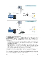
The data logger can be connected to the local network via
Ethernet
(default) or
Wi-Fi
(the two interfaces are alternatives, they can not be used simultaneously).
For the Ethernet mode, connect the RJ45 connector of the data logger to a socket of
the local network via a standard Ethernet cable.
The data loggers are preset to get a dynamic IP address from the network DHCP server.
The data loggers with LCD display the IP address (see pag. 5). For the data loggers
without LCD, the IP address can be displayed on the PC by using the
HDServer1
soft-
ware, which can automatically detect the data loggers connected to the network. A static
IP address can be set by using the web server feature of the data logger (see chapter 5)
or the HD35AP-S application software.
To connect the data logger to a Wi-Fi network, you must first change the setting of the
data logger interface by connecting the data logger to the PC via Ethernet and using
the web server feature of the data logger (see the panel
CONNECTIVITY >> NETWORK
in paragraph 5.3) or the HD35AP-S software. Alternatively, connect the data logger to
the PC via USB through the internal mini-USB connector (open the housing of the in-
strument by unscrewing the 4 front screws, the mini-USB connector is located to the
right of the display) and use the HD35AP-S software.
The data logger can be accessed from any PC of the local network. To download the da-
ta in a database, the
HD35AP-S
(it allows connecting one data logger at a time) or
HDServer1
(it allows connecting several data loggers simultaneously) application soft-
ware and the
MySQL
database management system (included in the HD35AP-S soft-
ware package) must be installed.
Thanks to the availability of two TCP/IP virtual ports, each of which can operate with
proprietary (for the connection with HD35AP-S software) or
MODBUS TCP/IP
proto-
col, and ten sockets (in total, to be divided between the two ports), the data logger
allows the simultaneous operation of two communication protocols (proprietary and
Modbus TCP/IP) and manages up to
10 “TCP/IP Client”
simultaneously. The default
setting of the ports is the following:
•
Port number = 5100 for proprietary protocol (8 sockets)
•
Port number = 502 for Modbus TCP/IP protocol (2 sockets)
If the local network is connected to Internet, the data can be regularly sent to an
FTP
address, to the
Cloud
and via
(as attachments).
Note
: if the communication with the Cloud is used, the maximum number of “clients”
with proprietary or
MODBUS TCP/IP
protocol is nine.
To configure the TCP/IP ports and the sending of data over the Internet, use the web
server feature of the data logger (see chapter 5) or the HD35AP-S software.
Restoring the factory LAN/WLAN configuration:
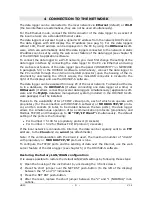
It is always possible to restore the default LAN/WLAN settings by following these steps:
1)
Open the housing of the instrument by unscrewing the 4 front screws.
2)
Place the short jumper over the NET RST push-button (to the left of the display)
between the “2” and “3” indications.
3)
Press the NET RST push-button.
4)
After the reset, replace the short jumper between the “2” and “1 (NORMAL)” indi-
cations.
Summary of Contents for HD50 14b7P TC
Page 52: ...HD50 52 V1 4 NOTES ...
Page 53: ...HD50 53 V1 4 NOTE ...
Page 54: ...HD50 54 V1 4 NOTE ...
Page 55: ......


