102
PMACPack Options and Accessories
Accessory 16D: Control Panel and Display Box
The Accessory 16D control panel provides all the means for using PMAC's dedicated hardware control
inputs and display outputs. It has nine toggle switches for the hardware functions, a 10-way rotary switch
for motor-/coordinate-system-select (1 to 8, all, and none), a handwheel encoder, an analog potentiometer,
a frequency generator, a 2x40 character alphanumeric LCD display, and 5 status LEDs.
Note:
A custom interface cable (no charge) is required for PMAC-Pack. Consult Delta
Tau before ordering.
Accessory 18: Thumbwheel Multiplexer Board
This accessory is a printed circuit board that provides the needed circuitry for PMAC to interface to 16
thumb wheel switches or similar inputs. Up to 32 thumb wheel multiplexer boards can be daisy-chained
together to permit the reading of up to 512 thumb wheel digits or other TTL level inputs (256 bytes).
Thumb wheels may be mounted directly on the board, or can be remotely connected.
to it. Note:
A custom interface cable (no charge) is required for PMAC-Pack. Consult Delta
Tau before ordering.
Alternatively, 8-position DIP switches may be mounted on the board for input.
•
ACC-18: Thumb wheel Multiplexer Board (bare)
•
OPT-1: Expansion Connector (for daisy-chain to next ACC-18)
•
OPT-2: One 8-Position DIP Switch (16 Max; in place of digit)
•
OPT-4: One Decimal Thumb wheel Digit (16 Max; specify loc.)
•
OPT-5: External Power Connector
•
OPT-6: Molex connectors w/ mates (16 Max; for remote digit)
An ACC-18 configuration sheet is available and can be used to define the required options and the
number and location of all the thumb wheel digits.
Accessory 20: Hand-Held Terminal
This accessory provides a hand-held or panel-mountable (~5" x 8" x 3/4") terminal for simple operational
communications needs. The terminal communicates with the serial port on the PMAC. It provides a
numeric keypad with 6 special programmable function keys; also an alphanumeric 2 x 24 LCD display.
Accessory 22: Extended Warranty
This "accessory" extends the warranty past the 1-year standard factory warranty, for a total of two years.
Accessory 25: Servo Evaluation Package
The Accessory 25 Servo Evaluation Package (SEP) is a program for IBM-PC compatible systems running
under DOS for autotuning and analysis of servo performance of PMACs with the Option 6 Extended
Servo Algorithm. A onetime purchase (site license) of this accessory is required for users purchasing the
Option 6 algorithm. The ACC-25 may be used for analysis of servo performance of PMACs with the
standard PID servo algorithm, but not for autotuning (the ACC-9DA can perform the autotuning). ACC-
25: Servo Evaluation Software for Extended Servo Algorithm on 3.5" diskette.
Accessory 26: Serial Communications Converter
Accessory 26 is a small circuit board that converts the RS-232 serial communications of the host
computer to the RS-422 serial communications format that many industrial equipment items, including
PMAC-Pack with OPT-9LPP, use. This conversion is performed through an optically isolated link,
Summary of Contents for PMAC Pack
Page 10: ...PMAC Pack Table of Contents vii ...
Page 11: ......
Page 16: ...PMAC Pack Overview 5 Figure 1 1 PMAC Pack Dimension ...
Page 27: ...PMAC Pack 16 Overview ...
Page 47: ...PMAC Pack 36 Getting Started ...
Page 51: ...PMAC Pack 40 Complying with European Community EMC Requirements ...
Page 53: ...PMAC Pack 42 PMACPack Custom Configuration Figure 4 1 PMAC Pack Disassembly ...
Page 70: ...PMAC Pack PMACPack Custom Configuration 59 Figure 4 4 PMAC Pack Assembly ...
Page 91: ...PMAC Pack 80 Circuit Diagrams Figure 7 2 Basic PMAC Pack Wiring Diagram ...
Page 92: ...PMAC Pack Circuit Diagrams Figure 7 3 PMAC Pack with Accessory 8D Option 2 Wiring Diagram ...
Page 93: ...PMAC Pack 82 Circuit Diagrams Figure 7 4 PMAC Pack with Accessory 8D Option 4A Wiring Diagram ...
Page 94: ...PMAC Pack Circuit Diagrams Figure 7 5 PMAC Pack with Option 9L Wiring Diagram ...
Page 95: ...PMAC Pack 84 Circuit Diagrams Figure 7 6 PMAC Pack with Accessory 28A Wiring Diagram ...
Page 96: ...PMAC Pack Circuit Diagrams Figure 7 7 PMAC Pack with Accessory 39 Wiring Diagram ...
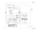
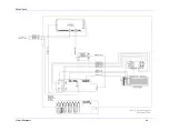
Page 97: ...PMAC Pack 86 Circuit Diagrams ...
Page 98: ...PMAC Pack Circuit Diagrams 87 ...
Page 99: ...PMAC Pack 88 Circuit Diagrams ...
Page 100: ...PMAC Pack Circuit Diagrams 89 ...
Page 101: ...PMAC Pack 90 Circuit Diagrams ...
Page 103: ...92 Acc 24E Acc 24EXP Expansion XP Pack Figure 8 1 Expansion Pack Installation ...
Page 106: ...PMAC Pack Acc 24E Acc 24EXP Expansion XP Pack 95 Figure 8 3 PMAC Pack Assembly ...
Page 109: ...98 Acc 24E Acc 24EXP Expansion XP Pack ...


