PMAC-Pack
Getting Started
19
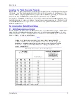
Installing the PMAC Executive Program
PMAC-Pack is set up and programmed serially through any IBM or 100% compatible personal computer
(PC). Delta Tau's PMAC Executive for DOS (ACC9DA) or PMAC Executive for Windows (ACC-9W)
software, or their accompanying PMAC Setup programs, PS or PSWIN, respectively, are recommended
for use in the initial establishment of communications and software setup of PMAC.
You should create a PMAC subdirectory on your computer's hard drive and install the zipped files using
the INSTALL utility included on the diskette. You may have to modify your system's CONFIG.SYS file
to provide the PMACEXEC program access to extended memory. (Refer to 3A0-PCPMAC-363 or 3A0-
0PEWIN-363 for details.)
Communication SwitchBank Setup
S1 - S4 Software Address Control
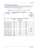
Switches S1-S4 on the front panel of the PMAC-Pack close or open PMAC-Lite jumpers E40-E43. These
jumpers in turn control the software address of the card, for serial addressing and for sharing the servo
clock over the serial connector. Card @0 address 0 sends the clock and cards @1-@F receive the clock.
Refer to Table 2-1 for address control settings.
Note:
Unless your system contains multiple PMAC-packs daisy-chained on a single
serial cable, S1-S4 should always be ON. The control must either be set up as @0
address 0, or receiving clock signals over the serial port from another PMACPack
that is set up as @0, or the WATCH-DOG timer will trip (red light ON) and the
control will shut down.
Table 2-1. Software Address Control Switch Settings
Card Address
Control Switches
Card Address
Default & Physical Layout
Location PMAC-Pack Front Panel
S1
S2
S3
S4
@0
ON ON ON ON
@0
OFF ON ON ON
@1
ON OFF ON ON
@2
OFF OFF ON ON
@3
ON ON OFF ON
@4
OFF ON OFF ON
@5
ON OFF OFF ON
@6
OFF OFF OFF ON
@7
ON ON ON OFF
@8
OFF ON ON OFF
@9
ON OFF ON OFF
@A
OFF OFF ON OFF
@B
ON ON OFF OFF
@C
OFF ON OFF OFF
@D
ON OFF OFF OFF
@E
OFF OFF OFF OFF
@F
Note: OFF
= OPEN
ON
= # Side of Switch
Summary of Contents for PMAC Pack
Page 10: ...PMAC Pack Table of Contents vii ...
Page 11: ......
Page 16: ...PMAC Pack Overview 5 Figure 1 1 PMAC Pack Dimension ...
Page 27: ...PMAC Pack 16 Overview ...
Page 47: ...PMAC Pack 36 Getting Started ...
Page 51: ...PMAC Pack 40 Complying with European Community EMC Requirements ...
Page 53: ...PMAC Pack 42 PMACPack Custom Configuration Figure 4 1 PMAC Pack Disassembly ...
Page 70: ...PMAC Pack PMACPack Custom Configuration 59 Figure 4 4 PMAC Pack Assembly ...
Page 91: ...PMAC Pack 80 Circuit Diagrams Figure 7 2 Basic PMAC Pack Wiring Diagram ...
Page 92: ...PMAC Pack Circuit Diagrams Figure 7 3 PMAC Pack with Accessory 8D Option 2 Wiring Diagram ...
Page 93: ...PMAC Pack 82 Circuit Diagrams Figure 7 4 PMAC Pack with Accessory 8D Option 4A Wiring Diagram ...
Page 94: ...PMAC Pack Circuit Diagrams Figure 7 5 PMAC Pack with Option 9L Wiring Diagram ...
Page 95: ...PMAC Pack 84 Circuit Diagrams Figure 7 6 PMAC Pack with Accessory 28A Wiring Diagram ...
Page 96: ...PMAC Pack Circuit Diagrams Figure 7 7 PMAC Pack with Accessory 39 Wiring Diagram ...
Page 97: ...PMAC Pack 86 Circuit Diagrams ...
Page 98: ...PMAC Pack Circuit Diagrams 87 ...
Page 99: ...PMAC Pack 88 Circuit Diagrams ...
Page 100: ...PMAC Pack Circuit Diagrams 89 ...
Page 101: ...PMAC Pack 90 Circuit Diagrams ...
Page 103: ...92 Acc 24E Acc 24EXP Expansion XP Pack Figure 8 1 Expansion Pack Installation ...
Page 106: ...PMAC Pack Acc 24E Acc 24EXP Expansion XP Pack 95 Figure 8 3 PMAC Pack Assembly ...
Page 109: ...98 Acc 24E Acc 24EXP Expansion XP Pack ...


