PMAC-Pack
24
Getting
Started
Note:
If PMAC is setup for Sign and Magnitude commands for Stepper motors, the
AENA line functions as the direction line. See the PMAC User's Manual and V-F
Converter manuals for further information on Stepper Motor interfacing.
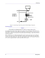
Amplifier Fault Signal (FAULT/)
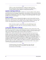
This input can take a signal from the amplifier so PMAC knows when the amplifier is having problems,
and can shut down action. The polarity is programmable with I-variable Ix25 (I125 for motor #1) and the
return signal is analog ground (AGND). FAULT/ is pin 2. With the default setup, this signal must actively
be pulled low for a fault condition. In this setup , if nothing is wired into this input, PMAC will consider
the motor not to be in a fault condition.
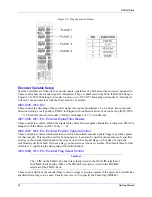
Flag Connection
PMAC has two inputs for each motor intended for the hardware overtravel limit switches. These lines
must actively be held low (to draw current through the LED in the optoisolator) in order for the motor to
be able to move. This requires the use of normally closed (or normally conducting, if solid state) limit
switches. These inputs are direction sensitive; they only stop movement in one direction.
Note:
PMAC-Pack's limits should be conventionally wired. The POSLIM input should
be connected to the positive end of travel, and the NEGLIM input to the negative
end of travel.
Limit Signals (NEGLIM And POSLIM)
PMAC-Pack has two inputs for each motor intended for the hardware overtravel limit switches. These
lines must actively be held low (to draw current through the optoisolator) in order for the motor to be able
to move. This requires the use of normally closed (or normally conducting, if solid state) limit switches.
These inputs are direction sensitive; they only stop movement in one direction.
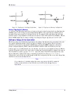
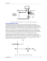
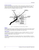
The PMAC-Packs optically isolated limits may be wired as either sinking or sourcing. Figure 2-4
illustrates connection of a limit input in a Sinking configuration. When the limit switch is normally
closed, current is pulled through the opto-isolator in the PMAC-PACK to ground. Figure 2-5 illustrates
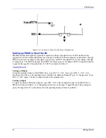
the connection of a limit input in Sourcing configuration. When the limit switch is normally closed,
current flows through the switch and into the PMAC-Pack’s optoisolator to the Flag Return which is tied
to common. The limit inputs are capable of operation at 12 to 24 DC voltage levels. If you desire to
maintain full isoV should be a separate voltage source. It is possible to operate using the +12V
available on pin 2 of each “Flags” connector as the voltage source. However, it should be noted that this
defeats the isolation circuitry causing the limit circuitry to be referenced to PMAC’s analog ground
(AGND) which is typically shared by the amplifier.
Note:
If the direction input of the encoder is ever changed, the wiring of the limit
switches must be changed as well. It is important to check and re-check the
direction sense of your limit inputs.
Summary of Contents for PMAC Pack
Page 10: ...PMAC Pack Table of Contents vii ...
Page 11: ......
Page 16: ...PMAC Pack Overview 5 Figure 1 1 PMAC Pack Dimension ...
Page 27: ...PMAC Pack 16 Overview ...
Page 47: ...PMAC Pack 36 Getting Started ...
Page 51: ...PMAC Pack 40 Complying with European Community EMC Requirements ...
Page 53: ...PMAC Pack 42 PMACPack Custom Configuration Figure 4 1 PMAC Pack Disassembly ...
Page 70: ...PMAC Pack PMACPack Custom Configuration 59 Figure 4 4 PMAC Pack Assembly ...
Page 91: ...PMAC Pack 80 Circuit Diagrams Figure 7 2 Basic PMAC Pack Wiring Diagram ...
Page 92: ...PMAC Pack Circuit Diagrams Figure 7 3 PMAC Pack with Accessory 8D Option 2 Wiring Diagram ...
Page 93: ...PMAC Pack 82 Circuit Diagrams Figure 7 4 PMAC Pack with Accessory 8D Option 4A Wiring Diagram ...
Page 94: ...PMAC Pack Circuit Diagrams Figure 7 5 PMAC Pack with Option 9L Wiring Diagram ...
Page 95: ...PMAC Pack 84 Circuit Diagrams Figure 7 6 PMAC Pack with Accessory 28A Wiring Diagram ...
Page 96: ...PMAC Pack Circuit Diagrams Figure 7 7 PMAC Pack with Accessory 39 Wiring Diagram ...
Page 97: ...PMAC Pack 86 Circuit Diagrams ...
Page 98: ...PMAC Pack Circuit Diagrams 87 ...
Page 99: ...PMAC Pack 88 Circuit Diagrams ...
Page 100: ...PMAC Pack Circuit Diagrams 89 ...
Page 101: ...PMAC Pack 90 Circuit Diagrams ...
Page 103: ...92 Acc 24E Acc 24EXP Expansion XP Pack Figure 8 1 Expansion Pack Installation ...
Page 106: ...PMAC Pack Acc 24E Acc 24EXP Expansion XP Pack 95 Figure 8 3 PMAC Pack Assembly ...
Page 109: ...98 Acc 24E Acc 24EXP Expansion XP Pack ...


