PMAC-Pack
PMACPack Mating and Connectors
71
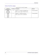
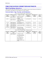
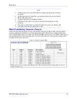
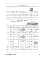
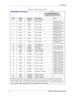
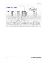
Table 6-8. FLT Relay Terminal Block
FLT Relay Terminal Block
Front View
Pin# Symbol Function
Description
Notes
1 NC
Output
Normally closed
FE/Watchdog output
See jumper E28
2 COM
Common
PMAC COMMON
3 NO
Output
Normally open
FE/Watchdog output
See jumper E28
Note:
This 3 pin terminal block provides an output (either normally open, or, normally closed) for
FE/Watchdog timer monitoring. Jumper E28 determines the functionality of this output.
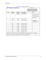
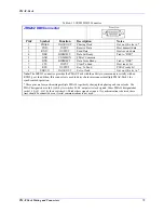
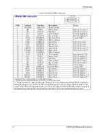
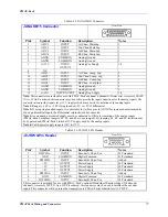
Table 6-9. TBAMP Terminal Block
TBAMP Terminal Block
Front View
Pin# Symbol Function
Description
ALT
Symbol
ALT
Function
ALT
Description
1 STEP
1
OUTPUT
1
st
Motor Pulse
(ref to Step GND)
OUT1+
Output
1st motor + lead
2 DIR
1 OUTPUT
1
st
Motor Direction
(ref to Step GND)
OUT1-
Output
1st motor - lead
3 STEP
2 OUTPUT 2
nd
Motor Pulse
(ref to Step GND)
OUT2+
Output
2nd motor +
lead
4 DIR
2 OUTPUT
2
nd
Motor Direction
(ref to Step GND)
OUT2-
Output
2nd motor -
lead
5 STEP
3 OUTPUT 3
rd
Motor Pulse
(ref to Step GND)
OUT3+
Output
3rd motor +
lead
6 DIR
3 OUTPUT
3
rd
Motor Direction
(ref to Step GND)
OUT3-
Output
3rd motor - lead
7 STEP
4 OUTPUT 4
th
Motor Pulse
(ref to Step GND)
OUT4+
Output
4th motor +
lead
8 DIR
4 OUTPUT
4
th
Motor Direction
(ref to Step GND)
OUT4-
Output
4th motor - lead
9
No Connect
No Connect
DB R-
Output
External shunt
reg. resistor; not
less than 10
Ω
10
No Connect
No Connect
DB R+
Output
External shunt
reg. resistor; not
less than 10
Ω
11
STEP GND
COMMON
Signal Return
PGND
Common
Bus Vground
12
STEP +V
INPUT
Optional Supply
(+5V to +24V)
A+48V
Input
DC bus supply
Note:
This terminal block provides connection of pulse and direction outputs for stepper axes or alternately
for either of PMAC-Pack's internal amplifier accessories (ACC8D OPT4PP or ACC8D OPT4APP).
Connection points are provided for motor leads, optional shunt regulator resistor, and amplifier power
supply.
Summary of Contents for PMAC Pack
Page 10: ...PMAC Pack Table of Contents vii ...
Page 11: ......
Page 16: ...PMAC Pack Overview 5 Figure 1 1 PMAC Pack Dimension ...
Page 27: ...PMAC Pack 16 Overview ...
Page 47: ...PMAC Pack 36 Getting Started ...
Page 51: ...PMAC Pack 40 Complying with European Community EMC Requirements ...
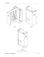
Page 53: ...PMAC Pack 42 PMACPack Custom Configuration Figure 4 1 PMAC Pack Disassembly ...
Page 70: ...PMAC Pack PMACPack Custom Configuration 59 Figure 4 4 PMAC Pack Assembly ...
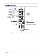
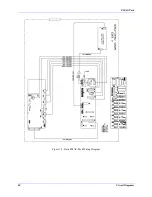
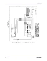
Page 91: ...PMAC Pack 80 Circuit Diagrams Figure 7 2 Basic PMAC Pack Wiring Diagram ...
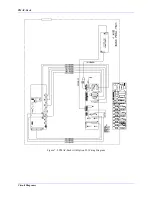
Page 92: ...PMAC Pack Circuit Diagrams Figure 7 3 PMAC Pack with Accessory 8D Option 2 Wiring Diagram ...
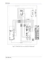
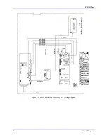
Page 93: ...PMAC Pack 82 Circuit Diagrams Figure 7 4 PMAC Pack with Accessory 8D Option 4A Wiring Diagram ...
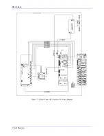
Page 94: ...PMAC Pack Circuit Diagrams Figure 7 5 PMAC Pack with Option 9L Wiring Diagram ...
Page 95: ...PMAC Pack 84 Circuit Diagrams Figure 7 6 PMAC Pack with Accessory 28A Wiring Diagram ...
Page 96: ...PMAC Pack Circuit Diagrams Figure 7 7 PMAC Pack with Accessory 39 Wiring Diagram ...
Page 97: ...PMAC Pack 86 Circuit Diagrams ...
Page 98: ...PMAC Pack Circuit Diagrams 87 ...
Page 99: ...PMAC Pack 88 Circuit Diagrams ...
Page 100: ...PMAC Pack Circuit Diagrams 89 ...
Page 101: ...PMAC Pack 90 Circuit Diagrams ...
Page 103: ...92 Acc 24E Acc 24EXP Expansion XP Pack Figure 8 1 Expansion Pack Installation ...
Page 106: ...PMAC Pack Acc 24E Acc 24EXP Expansion XP Pack 95 Figure 8 3 PMAC Pack Assembly ...
Page 109: ...98 Acc 24E Acc 24EXP Expansion XP Pack ...

