PMAC-Pack
PMACPack Mating and Connectors
73
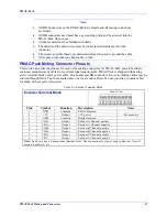
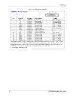
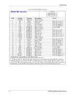
Table 6-11. JPAN 26-Pin Connector
JPAN 26-Pin Connector
Front View
Pin# Symbol Function
Description
Notes
1 +5V
OUTPUT
+5V Power
For remote panel
2
FPD0/
INPUT
Motor/C.S. Select Bit 0
Low is true
3
FPD1/
INPUT
Motor/C.S. Select Bit 1
Low is true
4
PREJ/
INPUT
Return to PREJOG Position
Low is "return"
Equiv to "J=" CMD
5
STEP/
INPUT
Step Through Program
Low is "step" equiv
to "S" or "Q"
6
HOME/
INPUT
Home Search Command
Low is "go home"
Equiv to "HM"
7
FPD2/
INPUT
Motor/C.S. Select Bit 2
Low is true
8
INIT/
INPUT
Reset PMAC
Low is "reset" equiv
to "$$$"
9
IPLD/
OUTPUT
In Position Ind. (CS)
Low lights led
10
ERLD/
OUTPUT
Fatal Follow Error (CS)
Low lights led
11 (SPARE)
NC
12
F1LD/
OUTPUT
Warn Follow Error (CS)
Low lights led
13
+5V
OUTPUT
+5V Power
For remote panel
14 GND COMMON
PMAC
Common
15
JOG-/
INPUT
Jog IN - DIR
Low is "jog -"
16
JOG+/
INPUT
Jog IN + DIR.
Low is "jog +"
17
STRT/
INPUT
Start Program Run
Low is "start" equiv
to "R CMD
18
STOP/
INPUT
Stop Program Run
Low is "stop" equiv
to "A
19
HOLD/
INPUT
Hold Motion
Low is "hold" equiv
to "H"
20
FPD3/
INPUT
Motor/C.S. Select Bit 3
Low is true
21
HWCA
INPUT
Handwheel Encoder A Channel
5V TTL SQ. Pulse
must use E23
(CHA2)
22
BRLD/
OUTPUT
Buffer Request Ind.
Low lights LED
23
WIPER
INPUT
Feed Pot Wiper
0 TO10V input must
use E72, E73
(CHA4)
24
HWCB
INPUT
Handwheel Encoder B Channel
5V TTL SQ. pulse
must use E22
(CHB2)
25
F2LD/
OUTPUT
Watchdog Timer
Low lights LED
The JPAN connector can be used to connect the Accessory 16 (Control Panel), or customer-provided I/O, to
the PMAC, providing manual control of PMAC functions via simple toggle switches. If the automatic
control panel input functions are disabled (I2=1), the inputs become general-purpose TTL inputs, and the
coordinate system (CS) specific outputs pertain to the host-addressed coordinate system.
Summary of Contents for PMAC Pack
Page 10: ...PMAC Pack Table of Contents vii ...
Page 11: ......
Page 16: ...PMAC Pack Overview 5 Figure 1 1 PMAC Pack Dimension ...
Page 27: ...PMAC Pack 16 Overview ...
Page 47: ...PMAC Pack 36 Getting Started ...
Page 51: ...PMAC Pack 40 Complying with European Community EMC Requirements ...
Page 53: ...PMAC Pack 42 PMACPack Custom Configuration Figure 4 1 PMAC Pack Disassembly ...
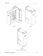
Page 70: ...PMAC Pack PMACPack Custom Configuration 59 Figure 4 4 PMAC Pack Assembly ...
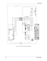
Page 91: ...PMAC Pack 80 Circuit Diagrams Figure 7 2 Basic PMAC Pack Wiring Diagram ...
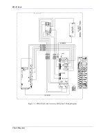
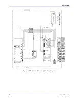
Page 92: ...PMAC Pack Circuit Diagrams Figure 7 3 PMAC Pack with Accessory 8D Option 2 Wiring Diagram ...
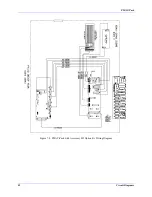
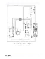
Page 93: ...PMAC Pack 82 Circuit Diagrams Figure 7 4 PMAC Pack with Accessory 8D Option 4A Wiring Diagram ...
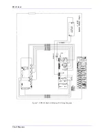
Page 94: ...PMAC Pack Circuit Diagrams Figure 7 5 PMAC Pack with Option 9L Wiring Diagram ...
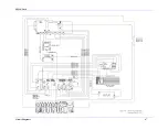
Page 95: ...PMAC Pack 84 Circuit Diagrams Figure 7 6 PMAC Pack with Accessory 28A Wiring Diagram ...
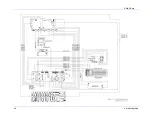
Page 96: ...PMAC Pack Circuit Diagrams Figure 7 7 PMAC Pack with Accessory 39 Wiring Diagram ...
Page 97: ...PMAC Pack 86 Circuit Diagrams ...
Page 98: ...PMAC Pack Circuit Diagrams 87 ...
Page 99: ...PMAC Pack 88 Circuit Diagrams ...
Page 100: ...PMAC Pack Circuit Diagrams 89 ...
Page 101: ...PMAC Pack 90 Circuit Diagrams ...
Page 103: ...92 Acc 24E Acc 24EXP Expansion XP Pack Figure 8 1 Expansion Pack Installation ...
Page 106: ...PMAC Pack Acc 24E Acc 24EXP Expansion XP Pack 95 Figure 8 3 PMAC Pack Assembly ...
Page 109: ...98 Acc 24E Acc 24EXP Expansion XP Pack ...

