background image

9

ASSEMBLING CUTTERHEAD GUARD

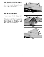
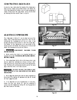
Position cutterhead guard (A) Fig. 7, on top cover of
machine. Align holes in cutterhead guard (A) Fig. 7, with
holes in top cover and fasten with six M6x12mm button
head screws (B), five of which are shown.

Fig. 7

ASSEMBLING DUST HOOD

A dust hood with a 5" opening is supplied with your
machine and is to be used when connecting the planer
to a dust collector or a central dust collection system.

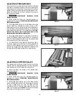
Position dust hood (A) Fig. 8, against the rear of the
machine and on top of cutterhead guard (B). Align the
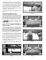
holes and fasten the dust hood (A) Fig. 9, to the
cutterhead guard (B) using seven M6x12mm button
head screws (C), four of which are shown.

Fig. 8

Fig. 9

A

B

A

B

A

C

B

Summary of Contents for 22-450

Page 1: ...odel 22 451 Single Phase PART NO 1349960 06 02 05 Copyright 2005 Delta Machinery To learn more about DELTA MACHINERY visit our website at www deltamachinery com For Parts Service Warranty or other Assistance please call 1 800 223 7278 In Canada call 1 800 463 3582 ...

Page 2: ...tal Mail Technical Service Manager Delta Machinery 4825 Highway 45 North Jackson TN 38305 IN CANADA 125 Mural St Suite 300 Richmond Hill ON L4B 1M4 Information regarding the safe and proper operation of this tool is available from the following sources Power Tool Institute 1300 Sumner Avenue Cleveland OH 44115 2851 www powertoolinstitute org National Safety Council 1121 Spring Lake Drive Itasca IL...

Page 3: ...LEMS The symbols below are used to help you recognize this information SAFETY GUIDELINES DEFINITIONS SOME DUST CREATED BY POWER SANDING SAWING GRINDING DRILLING AND OTHER CONSTRUCTION ACTIVITIES contains chemicals known to cause cancer birth defects or other reproductive harm Some examples of these chemicals are lead from lead based paints crystalline silica from bricks and cement and other masonr...

Page 4: ...to the machine and or injury may result 13 USE RECOMMENDED ACCESSORIES The use of accessories and attachments not recommended by Delta may cause damage to the machine or injury to the user 14 USE THE PROPER EXTENSION CORD Make sure your extension cord is in good condition When using an extension cord be sure to use one heavy enough to carry the current your product will draw An undersized cord wil...

Page 5: ...can cause injury 14 ALLOWTHECUTTERHEADTOREACHFULLSPEED before feeding a workpiece Changing speeds while planing can cause kickback 15 WHEN PLANING BOWED STOCK place the concave cup down side of the stock on the table and cut with the grain to prevent kickback 16 DO NOT FEED A WORKPIECE that is warped contains knots or is embedded with foreign objects nails staples etc Kickback can occur 17 DO NOT ...

Page 6: ...ilding s elecrical system All wiring must be done by a qualified electrician and conform to the National Electric Code and all local codes and ordinances For wiring instructions see section ELECTRICAL CONNECTIONS in this manual LVC MAGNETIC MOTOR CONTROL If you purchased a machine that has a Low Voltage Magnetic Motor Control System refer to its instruction manual for installation guidance MOTOR S...

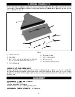
Page 7: ...tainer mounted to a shipping skid Remove the wooden crate from around the machine The planer is shipped with the motor motor pulleys and belts assembled to the machine Fig 2 illustrates the loose items supplied with the machine A B C D E F G H Fig 2 A Cutterhead Guard B Dust Hood C M6 x 1 x 12mm Button Head Screws for fastening the cover and dust hood to the machine 13 D Knife setting gage E Handw...

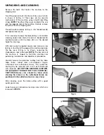
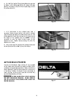
Page 8: ...n wrench supplied loosen and remove screw E Fig 5 from the left top edge of the machine and raise the top cover F Fig 6 as shown exposing the chipbreakers and cutterhead NOTE The top cover of the machine is hinged to facilitate cleaning and performing maintenance and adjustment procedures Carefully remove the protective coating from the table table rollers infeed roller anti kickback fingers cutte...

Page 9: ...EMBLING DUST HOOD A dust hood with a 5 opening is supplied with your machine and is to be used when connecting the planer to a dust collector or a central dust collection system Position dust hood A Fig 8 against the rear of the machine and on top of cutterhead guard B Align the holes and fasten the dust hood A Fig 9 to the cutterhead guard B using seven M6x12mm button head screws C four of which ...

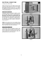
Page 10: ...plying power to the machine jog the power on and off to check if the cutterhead is rotating correctly If the cutterhead is not rotating correctly interchange any two of the three power lines connected to terminals F G and K Fig 12 NOTE The three phase motor is also capable of being wired for 440 volt operation but this connection must be done by a qualified electrician and conform to the National ...

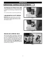
Page 11: ...ght setting IMPORTANT For best results setting of the table should always be made from the bottom to the up position Fig 15 A B C C A B OPERATION OPERATIONAL CONTROLS AND ADJUSTMENTS STARTING AND STOPPING THE PLANER 1 The power switch A Fig 13 is located on the front of the planer To turn the machine on push the START button 2 To turn the machine off push the stop button B LOCKING SWITCH IN OFF PO...

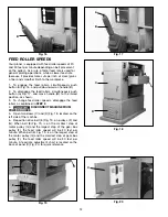
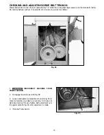
Page 12: ...A Fig 17 and move handle B to the raised position as shown 3 To change feed roller speeds disengage the feed rollers as explained in STEP 2 4 DISCONNECT MACHINE FROM POWER SOURCE 5 Open two doors C and D Fig 18 located on the left side of the machine 6 Reposition drive belt E Fig 19 on pulleys F and G When belt E Fig 19 is on the smallest step of motor pulley G and the largest step of the gear box...

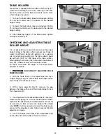
Page 13: ...to 005 above the table surface When planing finish stock the table rollers should be set low 001 above or level with the table surface To check and adjust the height of the table rollers proceed as follows Fig 22 Fig 23 Fig 24 1 DISCONNECT MACHINE FROM POWER SOURCE 2 With the table rollers in the lowest position lay a straight edge A Fig 22 across both table rollers B on the left side of the table...

Page 14: ...to the adjustment nuts Tighten locknut G Fig 26 after the adjustment is made 8 Check and adjust the height of the outfeed table roller on the other side of the table in the same manner ANTI KICKBACK FINGERS A series of anti kickback fingers A Fig 27 are provided on the infeed end of the planer to prevent kickback of the workpiece during planing operations These anti kickback fingers operate by gra...

Page 15: ... If an adjustment is necessary proceed as follows Fig 28 1 DISCONNECT MACHINE FROM POWER SOURCE 2 Disengage feed roller lever B Fig 28 3 Loosen and tighten two adjustment nuts C Fig 29 to move motor plate up or down as necessary to increase or decrease drive belt tension Tighten both adjustment nuts C against plate D Fig 29 after adjustment is made 4 Close both side panels Fig 29 A B C D ...

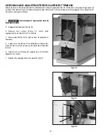
Page 16: ...ary proceed as follows 1 DISCONNECT MACHINE FROM POWER SOURCE 2 Engage feed roller lever D Fig 30 3 Remove four screws E Fig 31 which hold engagement lever boot F to the machine 4 Raise boot F Fig 32 to gain access to adjustment hardware 5 Loosen jam nut G Fig 32 and tighten or loosen ad justment hex nut H as necessary to adjust feed roller belt tension 6 Tighten jam nut G Fig 32 against hex nut H...

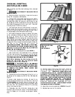
Page 17: ...s snug turn each of the ten locking screws F Fig 34 COUNTERCLOCKWISE UNTIL THE KNIVES ARE SECURE IN THE CUTTERHEAD NOTE When tightening the knife locking screws F tighten the end screws first then proceed inward toward the center of the cutterhead IF THE KNIVES ARE TO BE REMOVED FOR SHARPENING OR REPLACEMENT EXTREME CARE SHOULD BE TAKEN AS THE KNIVES ARE VERY SHARP TO REMOVE THE KNIVES WEAR GLOVES...

Page 18: ...st the chipbreakers proceed as follows 1 DISCONNECT MACHINE FROM POWER SOURCE 2 Make certain the knives are adjusted properly as explained in section CHECKING REPLACING AND RE SETTING KNIVES 3 Place gage block B Fig 38 on the table surface and directly under the cutterhead as shown Using a 040 feeler gage C Fig 38 placed on top of the gage block raise the table until cutterhead knife D touches the...

Page 19: ... pressure bar D Fig 41 should just touch the top of gage block B Check the opposite end of the pressure bar in the same manner 5 If an adjustment to the height of the pressure bar is necessary loosen lock nut E Fig 42 and turn adjustment screw F until the bottom of pressure bar D Fig 41 just touches top of gage block B Repeat the adjustment at the other end of the pressure bar in the same manner A...

Page 20: ...feed roller proceed as follows 1 DISCONNECT MACHINE FROM POWER SOURCE 2 Make certain the knives are adjusted properly as explained in section CHECKING ADJUSTING AND REPLACING KNIVES 3 Place gage block A Fig 46 on the table directly under the cutterhead B Using a 040 feeler gage C placed on top of the gage block A raise the table until the cutterhead knife just touches feeler gage A when the knife ...

Page 21: ... distance from table to cutterhead should be identical 5 If the table is not parallel to the cutterhead lower boot B Fig 51 which is located underneath the table NOTE Table elevating handwheel must be unlocked when making this adjustment 6 Loosen lock screw C Fig 51 and with large pliers D turn adjustment sleeve E as necessary until table is paralell with the cutterhead Tighten lock screw C after ...

Page 22: ...g or bowing repeat STEP 1 and true up one face 3 When planing long stock provide table extensions to support the infeed and outfeed end of the workpiece 4 Plane with the grain only and keep planer table clean Occasionally wax the table surface to reduce friction during the planing operation 5 Cross cut to Final Length Cross cut lumber to final length THE KNIVES ON THE PLANER WILL NOT WEAR EVENLY I...

Page 23: ...ons Please visit our Web Site www deltamachinery com for a catalog or for the name of your nearest supplier Since accessories other than those offered by Delta have not been tested with this product use of such accessories could be hazardous For safest operation only Delta recommended accessories should be used with this product ACCESSORIES SERVICE Two Year Limited New Product Warranty Delta will ...

Page 24: ...23 7278 y le dirigirán al Centro de Servicio de Fábrica Porter Cable Delta más cercano ARIZONA Phoenix 85013 2906 4501 N 7th Ave Phone 602 279 6414 Fax 602 279 5470 CALIFORNIA Ontario 91761 Los Angeles 3949A East Guasti Road Phone 909 390 5555 Fax 909 390 5554 San Diego 92111 7290 Clairemont Mesa Blvd Phone 858 279 2011 Fax 858 279 0362 San Leandro 94577 Oakland 3039 Teagarden Street Phone 510 357...

Reviews: