13
DEPTH OF CUT ADJUSTMENT
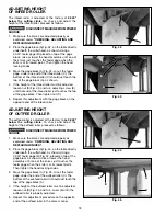
The depth of cut on your planer is controlled by raising
or lowering the head assembly (A) Fig. 22, which
contains the cutterhead and feed rollers. The head
assembly (A) moves on four precision ground steel
columns, three of which are shown at (B). To adjust for
depth of cut, simply loosen the two head assembly lock
knobs, one of which is shown at (C), and turn the head
raising and lowering handwheel (D). Turning the
handwheel (D) clockwise, raises the head assembly and
counterclockwise, lowers the head assembly. Then
tighten the two head assembly lock knobs (C).
The maximum depth of cut when planing stock narrower
than 6 inches wide is 3/16" when the stock is run
through the planer on one side or the other of the
cutterhead. A limiter (E) Fig. 22, is provided to limit the
depth of cut to 1/8" on stock wider than 6 inches.
Fig. 22
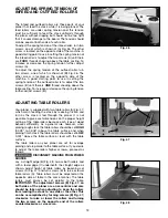
Fig. 23
Fig. 24
FEED SPEED CONTROL
CHANGE SPEEDS ONLY WHILE THE
MOTOR IS RUNNING. DO NOT CHANGE SPEEDS
WHILE PLANING.
Two feed roll speeds of 16 and 30 feet per minute are
provided with your planer. Generally speaking, the
slower feed rate provides more cuts per inch, thus a
finer, smoother finish of the workpiece is obtained. A
good rule to follow would be to operate the machine at
the faster feed rate for general planing and switch to the
slower feed rate for the final finished dimension of the
workpiece. When planing wide stock (wider than 8")
particularly in hard wood, the slower feed speed is more
desirable as there is less strain on the motor and a better
finish is obtained since there are more cuts per inch of
stock length.
When the shifter knob (A) Fig. 24, is pushed all the way
in as shown, the feed speed will be 30 feet per minute.
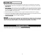
Fig. 25
Fig. 26
When the shifter knob (A) Fig. 25, is pulled all the way
out as shown, the feed speed will be 16 feet per minute.
When the shifter knob (A) Fig. 26, is in the center
(neutral) position as shown, the machine will stop
feeding.
D
B
B
B
C
A
A
E
A
A


