background image

7

FOREWORD

Delta Models 22-785 and 22-785X are 15" (381mm) Planers with adjustable feed rate for optimum planing under load.
They have the following cutting capacities; 15" (381mm) width, 6½" (165mm) thickness and 1/8" (5mm) depth of cut. 

FUNCTIONAL DESCRIPTION

EXTENSION CORDS

Use proper extension cords. Make sure

your extension cord is in good condition and is a 3-wire
extension cord which has a 3-prong grounding type
plug and matching receptacle which will accept the
machine’s plug. When using an extension cord, be sure
to use one heavy enough to carry the current of the
machine. An undersized cord will cause a drop in line
voltage, resulting in loss of power and overheating. Fig.
D-1, shows the correct gauge to use depending on the
cord length. If in doubt, use the next heavier gauge. The
smaller the gauge number, the heavier the cord.     

Fig. D-1

MINIMUM GAUGE EXTENSION CORD

RECOMMENDED SIZES FOR USE WITH STATIONARY ELECTRIC MACHINES

Ampere

Total Length

Gauge of

Rating

Volts

of Cord in Feet

Extension Cord

0-6

240

up to 50

18 AWG

0-6

240

50-100

16 AWG

0-6

240

100-200

16 AWG

0-6

240

200-300

14 AWG

6-10

240

up to 50

18 AWG

6-10

240

50-100

16 AWG

6-10

240

100-200

14 AWG

6-10

240

200-300

12 AWG      

10-12

240

up to 50

16 AWG

10-12

240

50-100

16 AWG

10-12

240

100-200

14 AWG

10-12

240

200-300

12 AWG

12-16

240

up to 50

14 AWG

12-16

240

50-100

12 AWG

12-16

240

GREATER THAN 100 FEET NOT RECOMMENDED

CARTON CONTENTS

Your new 15" Planer is shipped complete in one box.
The machine is very heavy. Care must be taken when
removing the machine. (See the section 

“LIFTING THE

MACHINE”

).

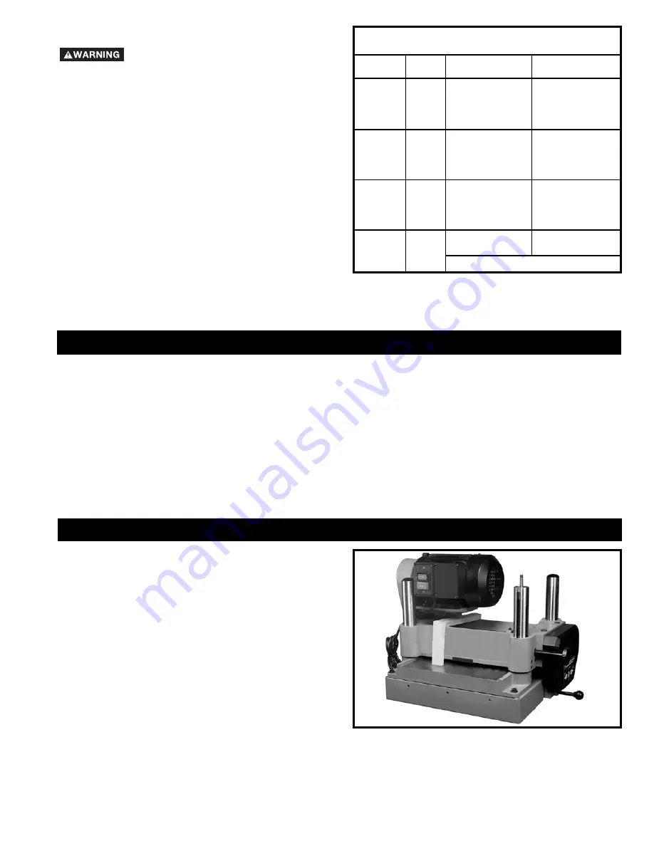
Figure 3 Illustrates the loose items supplied with your
machine.

Fig. 2

NOTICE: 

The photo on the manual cover illustarates the current production model. All other illustrations contained in

the manual are representative only and may not depict the actual labeling or accessories included. These are are
intended to illustrate technique only.

Summary of Contents for 22-785

Page 1: ...Copyright 2005 Delta Machinery To learn more about DELTA MACHINERY visit our website at www deltamachinery com For Parts Service Warranty or other Assistance please call 1 800 223 7278 In Canada call 1 800 463 3582 Shown with Delta accessory planer stand and roller extension tables ...

Page 2: ...tal Mail Technical Service Manager Delta Machinery 4825 Highway 45 North Jackson TN 38305 IN CANADA 125 Mural St Suite 300 Richmond Hill ON L4B 1M4 Information regarding the safe and proper operation of this tool is available from the following sources Power Tool Institute 1300 Sumner Avenue Cleveland OH 44115 2851 www powertoolinstitute org National Safety Council 1121 Spring Lake Drive Itasca IL...

Page 3: ...LEMS The symbols below are used to help you recognize this information SAFETY GUIDELINES DEFINITIONS SOME DUST CREATED BY POWER SANDING SAWING GRINDING DRILLING AND OTHER CONSTRUCTION ACTIVITIES contains chemicals known to cause cancer birth defects or other reproductive harm Some examples of these chemicals are lead from lead based paints crystalline silica from bricks and cement and other masonr...

Page 4: ...e to the machine and or injury may result 13 USE RECOMMENDED ACCESSORIES The use of accessories and attachments not recommended by Delta may cause damage to the machine or injury to the user 14 USE THE PROPER EXTENSION CORD Make sure your extension cord is in good condition When using an extension cord be sure to use one heavy enough to carry the current your product will draw An undersized cord w...

Page 5: ...nto the knives 13 DO NOT STAND IN LINE OF THE WORKPIECE Kickback can cause injury 14 ALLOWTHECUTTERHEADTOREACHFULLSPEED before feeding a workpiece Changing speeds while planing can cause kickback 15 WHEN PLANING BOWED STOCK place the concave cup down side of the stock on the table and cut with the grain to prevent kickback 16 DO NOT FEED A WORKPIECE that is warped contains knots or is embedded wit...

Page 6: ...E THE MACHINE IN DAMP LOCATIONS Your machine is wired for 240 volts 60 HZ alternating current Before connecting the machine to the power source make sure the switch is in the OFF position THIS MACHINE MUST BE GROUNDED WHILE IN USE TO PROTECT THE OPERATOR FROM ELECTRIC SHOCK NOTE In Canada the use of a temporary adapter is not permitted by the Canadian Electric Code IN ALL CASES MAKE CERTAIN THAT T...

Page 7: ... EXTENSION CORD RECOMMENDED SIZES FOR USE WITH STATIONARY ELECTRIC MACHINES Ampere Total Length Gauge of Rating Volts of Cord in Feet Extension Cord 0 6 240 up to 50 18 AWG 0 6 240 50 100 16 AWG 0 6 240 100 200 16 AWG 0 6 240 200 300 14 AWG 6 10 240 up to 50 18 AWG 6 10 240 50 100 16 AWG 6 10 240 100 200 14 AWG 6 10 240 200 300 12 AWG 10 12 240 up to 50 16 AWG 10 12 240 50 100 16 AWG 10 12 240 100...

Page 8: ... 13 14 15 16 UNPACKING AND CLEANING Carefully unpack the machine and all loose items from the shipping container s Remove the protective coating from all unpainted surfaces This coating may be removed with a soft cloth moistened with kerosene do not use acetone gasoline or lacquer thinner for this purpose After cleaning cover the unpainted surfaces with a good quality household floor paste wax ASS...

Page 9: ... VERY HEAVY AND A MINIMUM OF FOUR PEOPLE WILL BE REQUIRED TO LIFT THE MACHINE AS FOLLOWS 2 Raise the cuttinghead A Fig 10 by turning the raising and lowering handwheel B clockwise and insert two 6 or 8 foot long 2 x 4 s C between the cuttinghead and table as shown Lower the cuttinghead just until it touches the 2 x 4 s C Fig 10 so that they are positioned solidly between the table and cuttinghead ...

Page 10: ...CONTROLS AND ADJUSTMENTS Fig 18 A B Fig 19 C STARTING AND STOPPING PLANER 1 The on off switch is located on the front of the planer To turn the machine ON push the START button A Fig 18 2 To turn the machine OFF push the STOP button B Fig 18 MAKE SURE THAT THE SWITCH IS IN THE OFF POSITION BEFORE PLUGGING IN THE POWER CORD IN THE EVENT OF A POWER FAILURE MOVE THE SWITCH TO THE OFF POSITION AN ACCI...

Page 11: ...EED CONTROL CHANGE SPEEDS ONLY WHILE THE MOTOR IS RUNNING DO NOT CHANGE SPEEDS WHILE PLANING Two feed roll speeds of 16 and 30 feet per minute are provided with your planer Generally speaking the slower feed rate provides more cuts per inch thus a finer smoother finish of the workpiece is obtained A good rule to follow would be to operate the machine at the faster feed rate for general planing and...

Page 12: ... Fig 29 between the motor plate and the top of the head casting as shown 3 Loosen the four screws C Fig 29 and pry up on motor plate until correct belt tension is obtained Correct tension is when there is approximately 1 4 deflection in the center span of the belts using light finger pressure Then tighten the three screws C and replace belt and pulley guard cover B Fig 28 Fig 28 Fig 29 B A A A D C...

Page 13: ...ten the five locking screws two of which are shown at K Fig 37 against the slot starting with the end screws first then the center screws until the knife is securely held in the cutterhead Tighten the remaining two knives in the same manner C D Fig 34 E F Fig 35 G Fig 36 J H Fig 37 L K M N 5 IF THE KNIVES ARE TO BE REMOVED FOR SHARPENING OR REPLACEMENT EXTREME CARE SHOULD BE TAKEN AS THE KNIVES AR...

Page 14: ...proceed as follows DISCONNECT MACHINE FROM POWER SOURCE 1 Make certain the knives are adjusted properly as explained under CHECKING ADJUSTING AND RE PLACING KNIVES 2 Place the gage block A Fig 39 on the table directly under the cutterhead as shown Using a 0 020 feeler gage B placed on top of the gage block raise or lower the head assembly until one of the knives just touches the feeler gage when t...

Page 15: ...nut D 5 Repeat this adjustment with the gage block on the opposite end of the infeed roller Fig 42 Fig 43 Fig 44 Fig 45 ADJUSTING HEIGHT OF OUTFEED ROLLER The outfeed roller is adjusted at the factory to be 0 040 below the cutting circle To check and adjust the height of the outfeed roller proceed as follows DISCONNECT MACHINE FROM POWER SOURCE 1 Make sure the knives are adjusted properly as ex pl...

Page 16: ...ith two table rollers A Fig 47 which aid in feeding the stock by reducing friction and turn as the stock is fed through the planer It is not possible to give exact dimensions on the proper height setting of the table rollers because each type of wood behaves differently As a general rule however when planing rough stock the table rollers should be set HIGH 0 003 to 0 005 above the table surface an...

Page 17: ...tfeed end of table 4 If head casting is not parallel to table tilt planer on its side as shown in Fig 51 Remove bolt C and loosen bolt D Fig 51 which will allow you to move the idler sprocket assembly E far enough to release tension on chain as shown in Fig 52 Remove chain from sprocket on end of headcasting that must be adjusted In this case chain has been removed from sprocket F 5 Turn sprocket ...

Page 18: ...warping or bowing repeat STEP 1 and true up one face 3 When planing long stock provide table extensions to support the infeed and outfeed end of the workpiece 4 For best results always engage cutterhead lock before planing plane with the grain only and keep planer table clean Occasionally wax table surface to reduce friction during the planing operation 5 Cross cut to Final Length Cross cut lumber...

Page 19: ...ier Porter Cable Delta Factory Service Centers and Delta Authorized Service Stations Please visit our Web Site www deltamachinery com for a catalog or for the name of your nearest supplier Since accessories other than those offered by Delta have not been tested with this product use of such accessories could be hazardous For safest operation only Delta recommended accessories should be used with t...

Page 20: ...23 7278 y le dirigirán al Centro de Servicio de Fábrica Porter Cable Delta más cercano ARIZONA Phoenix 85013 2906 4501 N 7th Ave Phone 602 279 6414 Fax 602 279 5470 CALIFORNIA Ontario 91761 Los Angeles 3949A East Guasti Road Phone 909 390 5555 Fax 909 390 5554 San Diego 92111 7290 Clairemont Mesa Blvd Phone 858 279 2011 Fax 858 279 0362 San Leandro 94577 Oakland 3039 Teagarden Street Phone 510 357...

Reviews: