20
HOW TO ADJUST THE TABLE ROLLERS
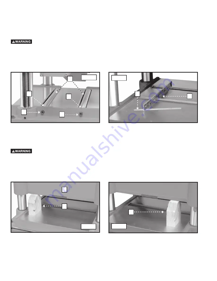
Your planer is supplied with two table rollers (A) Fig. 56 that help feed the stock by reducing friction. Since each type
of wood behaves differently, exact dimensions of the proper height setting are not available. generally, however, when
planing a rough workpiece, set the table rollers
HIGH
(0.003" to 0.005") (.08 mm to .13 mm) above the table surface.
When planing a finish workpiece, set the table rollers
LOW
(0.001") (.03 mm) above the table surface or level with
the table surface. The table rollers on your planer are set for average planing and are parallel to the table surface. To
change that setting:
Place a straight edge (B) Fig. 57 across both rollers. Use a feeler gauge (C) underneath the straight edge. Adjust the
height of the table rollers by loosening set screws (D) Fig. 56, and turn screws (E) to raise or lower table rollers (A). Adjust
the table rollers on the opposite side of table in the same manner. Always set the table rollers parallel to the table.
IMPORTANT:
The adjustment screws (E) Fig. 56 on both sides of the planer are eccentrics. To keep the rollers from
leading the stock to one side or the other, turn the screws (E) Fig. 56 on opposite ends of the rollers to raise or lower
the table.
Disconnect the machine from the power source.
A
E
D
Fig. 56
Fig. 57
E
D
C
B
HOW TO ADJUST THE CUTTINGHEAD PARALLEL TO THE TABLE
The cuttinghead was set parallel to the table at the factory and no further adjustment should be necessary. If your
machine is planing a taper, first check to see if the knives are set properly. Then check to see if the cuttinghead is set
parallel to the table.
1. Place the gauge block (A) Fig. 58 on the table directly under the front edge of head casting (B). Lower the head
casting until the front edge of the head casting (B) touches the top of the gauge block.
2. Move the gauge block (A) Fig. 59 to the opposite end of table. The distance from the table to the edge of the head
casting should be the same.
3. Repeat
STEPS 1
and
2
on the outfeed end of table.
Disconnect the machine from the power source.
Fig. 58
Fig. 59
A
B
A
4. If the head casting is not parallel to the table, tilt the planer on its side. Remove the bolt (C) Fig. 60 and loosen the
bolt (D). Move the idler sprocket assembly (E) far enough to release the tension on the chain (Fig. 61). Remove the
chain from the sprocket on the end of the headcasting you will adjust. In this case chain has been removed from
the sprocket (F) Fig. 61.
5. Turn the sprocket (F) Fig. 61 by hand to adjust it with the other three corners.


