Page 2
210208 Rev. A
(OPTIONAL) 1/4” MIP TAIL
(NOT INCLUDED)
(OPTIONNEL) MAMELON DE
RACCORDEMENT 1/4” MIP,
(NON FOURNI)
(OPCIONAL) COLA DE 1/4”
MIP (NO INCLUIDA)
BULLNOSE LAV. SUPPLY (NOT INCLUDED)
TUBE SOUPLE À TETE CONIQUE POUR LAVABO (NON FOURNI)
78%2'(680,1,6752'(&$%(=$5('21'($'$3$5$
LAVAMANOS (NO INCLUIDO)
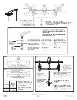
51mm (2.0”)
32mm (1.25”) MIN.
+2/(6
3 TROUS
$*8-(526
27mm (1.06”) MAX.
1. INSTALLER d’abord la
rondelle en DURITE (surface
texturée abrasive) entre le bec
(ou la base excentrée pour bec
en col-de-cygne) et le dessus
de l’évier.
2. INSTALLER la 2e rondelle en
DURITE contre la surface
inférieure de l’évier entre l’évier
et la rondelle de fibre.
3. SERRER solidement l’écrou
hexagonal en laiton coulé contre
la rondelle de fibre.
1.
COLOQUE primero la aran-
dela DURITE (arandela de tejido
áspero abrasivo) entre el tubo de
salida (o base del cuerpo del
tubo) y la parte de arriba del lava-
manos.
2.
INSTALE la segunda arandela
DURITE contra la parte interior
del lavamanos entre éste y el
empaque de fibra.
3.
APRIETE firmemente la
contratuerca
KH[DJRQDO
de metal
fundido contra el empaque de fibra.
TO INSURE A RIGID SPOUT CONNECTION
POUR GARANTIR UN RACCORDEMENT DE
BEC SOLIDE
PARA ASEGURAR UNA CONEXIÓN RÍGIDA
DEL TUBO DE SALIDA
FOR GOOSENECK SPOUT LESS POP-UP
POUR BEC EN COL-DE-CYGNE SANS VIDAGE MÉCANIQUE
3$5$78%2&8(//2'(*$1=26,1'(6$*h($8720È7,&2
)25´&(175(6$66833/,('
POUR INSTALLATION DE 12” D’ENTRAXE
FOURNIE EN STANDARD
PARA LOS CENTROS DE 12” SUMINISTRADOS
“D” = TUBE CUTOFF DIMENSION (EACH END)
«D» = LONGUEUR DE TUBE À COUPER
(À CHAQUE EXTRÉMITÉ)
“D” = DIMENSIÓN DE CORTE DEL TUBO (CADA EXTREMO)
“D” INCHES
«D» POUCES
“D” PULGADAS
FAUCET CENTRES
ENTRAXE DE LA
ROBINETTERIE
CENTROS DE
LAS LLAVES
FOR CAST SPOUT AND FOR
GOOSENECK SPOUT WITH POP-UP
POUR BEC CONVENTIONNEL ET
BEC EN COL-DE-CYGNE AVEC
VIDAGE MÉCANIQUE
PARA TUBO DE SALIDA CONVEN-
CIONAL Y PARA TUBO DE SALIDA
CUELLO DE GANSO CON DESAG
h
E
AUTOM
È7,
CO
1. INSTALL spout
RQIL[WXUH
2. CUT copper tubes to
required length per
Fig. C.
3. ASSEMBLE centre
tee/tubes (Fig.C)
to end bodies.
4. THREAD slotted
centre tee post
into bottom of
spout with a
slotted screwdriver.
1. INSTALLER le bec
sur le lavabo.
2. DÉCOUPER les
tuyaux de cuivre à la
longueur requise
(Fig. C).
1. COLOQUE el tubo de agua en la
instalación.
2. CORTE los tubos de cobre del largo
requerido en la Fig. C.
3. ENSAMBLE el centro de la Te/tubos
)LJ&DORVH[WUHPRVGHORVFXHUSRV
4. ATORNILLE el poste de centro ranurado
de la Te dentro del fondo del tubo de
agua con un destornillador.
Fig. B
Fig. C
0”
1”
2”
3”
114mm (4.5”)
3. ASSEMBLER le raccord en T central/
tuyaux (Fig. C) aux embouts.
4. METTRE EN PLACE le montant du
raccord en T en le fixant dans la partie
inférieure du bec à l’aide d’un tournevis
pour écrous à fente.
Fig. A
Fig. D
12”
10”
8”
6”
1.
PLACE first DURITE (coarse
woven abrasive) washer between
the spout (of offset spout body)
and the top of the
VLQN
.
2
INSTALL second DURITE
washer against the underside
of the
VLQN
between the
VLQN
and
the fibre
JDVNH
t.
3.
TIGHTEN the cast brass he
[
ORFNQX
t very securely against
the fibre
JDVNH
t.
),%5(
FIBRE
(03$48(
DE FIBRA
'85,7(
DURITE
$5$1'(/$6
DURITE
w w w . s p e c s e l e c t . c o m


