14
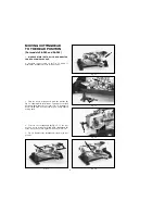
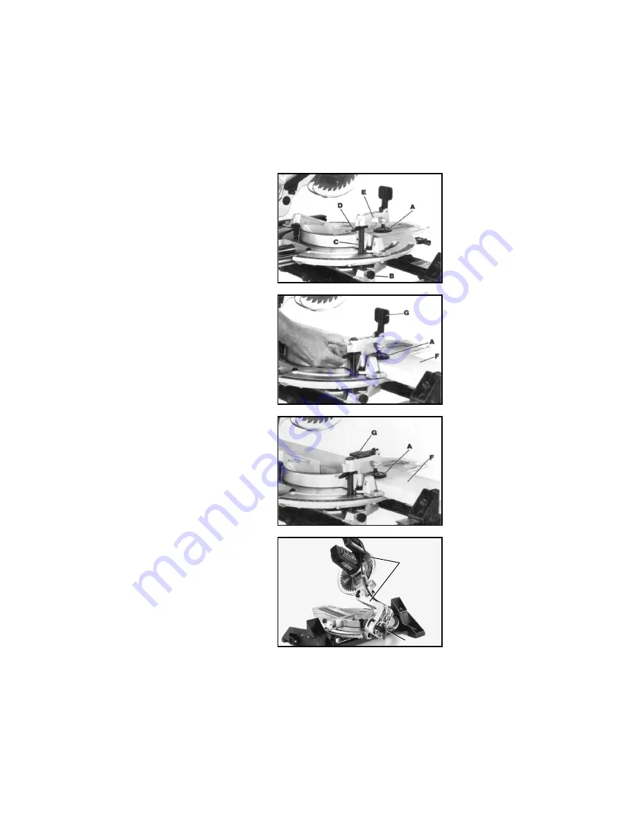
Fig. 38
Fig. 39
Fig. 40
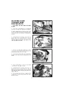
Fig. 41
WORK CLAMP OPERATION
1.
The height of the work clamp (A) Fig. 38, can be
adjusted by loosening lock knob (B) and moving post (C)
up or down, or compressing lock lever (D) and sliding
clamp body (E) up or down. After height of clamp (A)
is adjusted, tighten lock knob (B) and/or release lock
lever (D).
2.
During operation, lower clamp (A) Fig. 39, until the
bottom of the clamp (A) lightly contacts top of workpiece
(F).
IMPORTANT: When lowering clamp (A) make
certain cam lever (G) is in the up position as shown.
3.
For final clamping of the workpiece (F) Fig. 40,
against the table, move cam lever (G) to the rear, as
shown. After cut is completed, lift lever (G). This will
raise clamp (A) slightly, allowing you to slide or remove
workpiece (F).
TILTING CUTTINGHEAD
FOR BEVEL CUTTING
The cuttinghead of your compound slide saw can be
tilted to cut any bevel angle from a 90 degree straight
cut-off to a 45 degree left bevel angle by loosening bevel
lock knob (A) Fig. 41, tilting cuttinghead (B) to the desired
angle, and tightening lock knob (A).
B
A
Summary of Contents for 36-240
Page 32: ...32 NOTES...

