8
3.
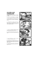
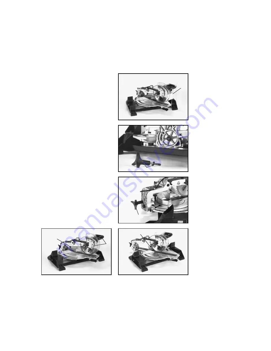
Find the bevel locking knob with flat washer (B)
Fig. 13, supplied with the machine. Thread bevel locking
knob and flat washer into hole (C) Fig. 13. Assembled
bevel locking knob is shown in (B) Fig. 14. Firmly tighten
locking knob.
Fig. 12
Fig. 13
Fig. 14
Fig. 16
Fig. 15
MOVING CUTTINGHEAD
TO THE REAR POSITION
(For models 36-240 and 36-250)
1.
MAKE CERTAIN THE TOOL IS DISCONNECTED
FROM THE POWER SOURCE
.
2.
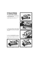
Carefully remove cable tie (A) Fig. 12, which is
holding the cuttinghead in the down position.
4.
To move the cuttinghead (D) Fig. 15, to the rear
position, loosen lock knob (E) and push cuttinghead (D)
to the rear position.Then tighten lock knob (E) Fig. 16.
5.
Fig. 16, illustrates the cuttinghead locked in the rear
position.
A
C
B
B
E
D
E
Summary of Contents for 36-240
Page 32: ...32 NOTES...

