background image

7

1.

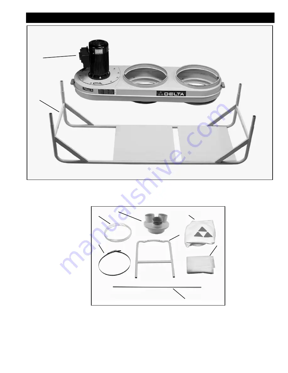
Motor and blower assembly

2.

Stand

1

2

Fig. 1

CARTON CONTENTS 

3

4

5

6

7

8

9

3.

Dust intake port

4.

Cloth-covered bag retainer ring (2)

5.

One micron upper filter bag (2)

6.

Six mil plastic lower bag (4)

7.

Legs (2)

8.

Bag retainer clamp (2)

9.

Bag hanging rod (2)

Fig. 1A

Summary of Contents for 50-761

Page 1: ...50 761 PART NO A03570 05 12 05 Copyright 2005 Delta Machinery To learn more about DELTA MACHINERY visit our website at www deltamachinery com For Parts Service Warranty or other Assistance please call...

Page 2: ...at this product NOT be modified and or used for any application other than for which it was designed If you have any questions relative to its application DO NOT use the product until you have written...

Page 3: ...in property damage It is important for you to read and understand this manual The information it contains relates to protecting YOUR SAFETY and PREVENTING PROBLEMS The symbols below are used to help y...

Page 4: ...the machine and or injury may result 13 USE RECOMMENDED ACCESSORIES The use of accessories and attachments not recommended by Delta may cause damage to the machine or injury to the user 14 USE THE PR...

Page 5: ...ellow stripes is the equipment grounding conductor If repair or replacement of the electric cord or plug is necessary do not connect the equipment grounding conductor to a live terminal Check with a q...

Page 6: ...REPRESENTATIVE ONLY AND MAY NOT DEPICT THE ACTUAL COLOR LABELING OR ACCESSORIES AND ARE INTENDED TO ILLUSTRATE TECHNIQUE ONLY FOREWORD The Delta Industrial Model 50 761 Dust Collector will connect to...

Page 7: ...ly 2 Stand 1 2 Fig 1 CARTON CONTENTS 3 4 5 6 7 8 9 3 Dust intake port 4 Cloth covered bag retainer ring 2 5 One micron upper filter bag 2 6 Six mil plastic lower bag 4 7 Legs 2 8 Bag retainer clamp 2...

Page 8: ...9 5mm Lockwasher for attaching casters to stand 4 15 5 16 8mm Flat washers for attaching legs to blower motor assembly and for the brackets 6 16 M4 sheet metal screw for dust intake port 4 17 5 16 8m...

Page 9: ...EP Place all four stand posts A Fig 3 into four legs B on motor blower assembly Make sure metal base plates D are arranged over the large dust collection holes C Fig 3 A B D C LEGS TO MOTOR BLOWER ASS...

Page 10: ...UP The steps so far will assemble the unit with the motor on top and dust intake ports on bottom as shown in Fig 4 This unit can be assembled with the intake port B Fig 5 in the up position by followi...

Page 11: ...ttom groove B Fig 9 It will be necessary to bend and fold the ring to fit it into place 3 Tug slightly on bag to eliminate any slack and to make sure there is a good fit so the bag will not detach dur...

Page 12: ...OTE See ACCESSORIES section of this manual NOTE Do not operate the dust collector with any of the holes in dust intake port C Fig 13 uncovered To cover a hole not being used by a hose place the flat i...

Page 13: ...OWER FAILURE PUSH THE STOP BUTTON AN ACCIDENTAL START UP CAN CAUSE INJURY LOCKING SWITCH IN THE OFF POSITION IMPORTANT When the machine is not in use the START button should be locked to prevent unaut...

Page 14: ...station with proof of purchase of the product within two years and provides Delta with reasonable opportunity to verify the alleged defect by inspection For all refurbished Delta product the warranty...

Page 15: ...15 NOTES...

Page 16: ...7278 y le dirigir n al Centro de Servicio de F brica Porter Cable Delta m s cercano ARIZONA Phoenix 85013 2906 4501 N 7th Ave Phone 602 279 6414 Fax 602 279 5470 CALIFORNIA Ontario 91761 Los Angeles...

Reviews: