14- ENG
D27449
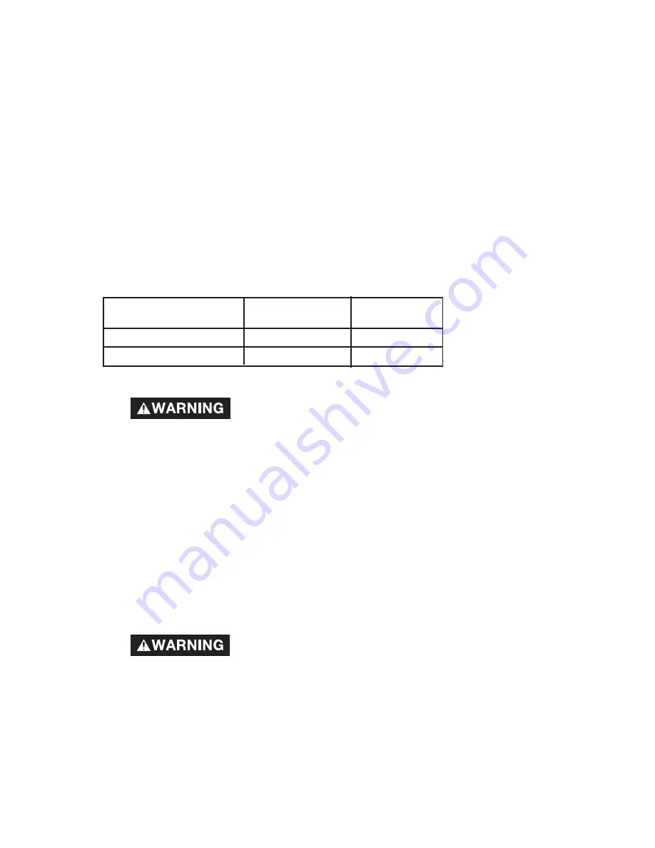
MAINTENANCE
Customer Responsibilities
Daily or after
each use
Before each use
Check Safety Valve
●
Drain Tank
●
To Check Safety Valve
If the safety valve does not work properly, over-
pressurization may occur, causing air tank rupture
or an explosion. Before starting compressor, pull the ring on the safety
valve to make sure that the safety valve operates freely. If the valve is
stuck or does not operate smoothly, it must be replaced with the
same type of valve.
To Drain Tank
1.
Set the On/Auto/Off lever to “OFF”.
2.
Pull the regulator knob out and turn counter-clockwise to set the outlet
pressure to zero.
3.
Remove the air tool or accessory.
4.
Pull ring on safety valve allowing air to bleed from the tank until tank
pressure is approximately 20 psi. Release safety valve ring.
5.
Drain water from air tank by opening drain valve (counter-clockwise) on
bottom of tank.
Water will condense in the air tank. If not drained,
water will corrode and weaken the air tank causing
a risk of air tank rupture.
6.
After the water has been drained, close the drain valve (clockwise). The air
compressor can now be stored.
NOTE
: If drain valve is plugged, release all air pressure. The valve can then be
removed, cleaned, then reinstalled.
How to Start:
1.
Turn the On/Auto/Off lever to “AUTO” and allow tank pressure to build.
Motor will stop when tank pressure reaches “cut-out” pressure.
2.
Pull the regulator knob out and turn clockwise to increase pressure. When
the desired pressure is reached push knob in to lock in place. The
compressor is ready for use.
NOTE:
Always operate the air compressor in well-ventilated areas free of
gasoline or other combustible vapors. If the compressor is being used to
operate a sprayer DO NOT place near the spray area.
Summary of Contents for 66-500-1
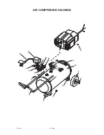
Page 20: ...20 ENG D27449 AIR COMPRESSOR DIAGRAM 21 5 13 16 4 3 9 10 1 11 15 6 14 12 8 7 7 17 20 18 19 2 ...
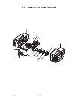
Page 22: ...22 ENG D27449 AIR COMPRESSOR PUMP DIAGRAM 1 15 20 14 16 9 12 7 4 10 11 13 8 6 5 3 21 2 18 ...
Page 70: ...70 FR D27449 DIAGRAMME DU POMPE 1 15 20 14 16 9 12 7 4 10 11 13 8 6 5 3 21 2 18 ...

