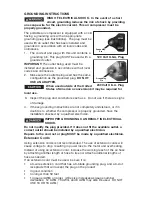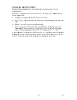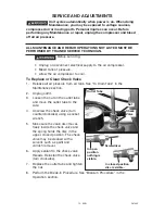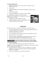
INSTALLATION
Location of the Air Compressor
Locate the air compressor in a clean, dry and well ventilated area. The air
compressor should be located at least 12" away from the wall or other
obstructions that will interfere with the flow of air. The air compressor pump
and shroud are designed to allow for proper cooling. The ventilation openings
on the compressor are necessary to maintain proper operating temperature. Do
not place rags or other containers on or near these openings.
HOW TO SET UP YOUR UNIT
9- ENG
D27449
ASSEMBLY (does not apply to all units)
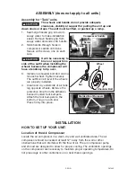
Assembly for “Tank” units
The wheels and handle do not provide adequate
clearance, stability or support for pulling the unit up and
down stairs or steps. The unit must be lifted, or pushed up a ramp.
1. Submerge handle grip into warm
soapy water to make installation
easier. Remove handle grip from
soapy water and slide onto handle.
2.
Slide handle through holes in
compressor saddle onto tabs.
Secure with screws, one on each
side.
It will be necessary to
brace or support one
side of the outfit when installing the
wheels because the compressor will
have a tendency to tip over.
3.
Install one shoulder bolt and one nut
for each wheel. Tighten securely.
The outfit will sit level if the wheels
are properly installed.
4.
Clean and dry underside of air tank
leg opposite wheels. Remove the
protective strip from the adhesive
backed molded foot bumpers.
Attach the foot bumpers to the
bottom of leg on each end.
Press firmly into place.
Wheel
Shoulder Bolt
Nut
Handle
Screw
Compressor Saddle
Tab
Molded Foot Bumpers
Summary of Contents for 66-500-1
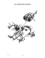
Page 20: ...20 ENG D27449 AIR COMPRESSOR DIAGRAM 21 5 13 16 4 3 9 10 1 11 15 6 14 12 8 7 7 17 20 18 19 2 ...
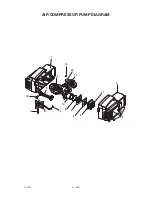
Page 22: ...22 ENG D27449 AIR COMPRESSOR PUMP DIAGRAM 1 15 20 14 16 9 12 7 4 10 11 13 8 6 5 3 21 2 18 ...
Page 70: ...70 FR D27449 DIAGRAMME DU POMPE 1 15 20 14 16 9 12 7 4 10 11 13 8 6 5 3 21 2 18 ...

