background image

7

Amplon Transformer Cabinet

No.

Description

9

The input circuit breaker will trip when the load exceeds the TFM-RT’s 

power rating.

10

The TFM-RT’s circuit breaker will trip when that the TFM-RT becomes 

overheated.

11

The input power cord is for connecting to the UPS.

z

z

TFM-RT-8/10K (TFM103R4RT2N035) Rear Panel

No.

Description

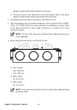
1

Load 1: 120V output receptacles (5-15/ 20R x 4). 

2

Load 2: 120V output receptacles (5-15/ 20R x 4).

3

Load 3: 208V output receptacles (L14-30R x 1).

4

Load 4: 208V output receptacles (L14-30R x 1).

5

The Load 1 circuit breaker will trip when the load exceeds the power 

rating.

6

The Load 2 circuit breaker will trip when the load exceeds the power 

rating.

OUTPUT SOCKET-2 / 20A MAX.

OUTPUT BREAKER-1

250V AC 20A

OUTPUT BREAKER-2

250V AC 20A

O

U

TP

U

BR

EAK

ER

-4

250

AC

 30

A

OUTPUT BREAKER

250V AC 50A

OUTPUT SOCKET-1 / 20A MAX.

TRANSFORMER 

PROTECTION 

BREAKER 8A

La

N

Lb

120V AC

120V AC

AC OUTPUT

Lc

Ld

208V AC

L1

208V AC

AC INPUT

L2

O

U

TP

U

BR

EAK

ER-

3

250

AC

 30

A

OUTPUT SOCKET-4

 30A MAX.

OUTPUT SOCKET-3

 30A MAX.

1

2

4

3

5

6

7

8

9

10

11

11

12

(Rear View)

Summary of Contents for Amplon TFM-RT Series

Page 1: ...www deltapowersolutions com Delta UPS Amplon Family User Manual The power behind competitiveness Transformer Cabinet 5 6 8 10 kVA ...

Page 2: ...f this product Any disposition duplication dissemination reproduction modification translation extraction or usage of this Manual in whole or in part is prohibited without the prior written permission of Delta Given that Delta will continuously improve and develop the product changes may be made to the information in this Manual at any time without obligation to notify any person of such revision ...

Page 3: ... 1 Installation Placement 9 4 2 Installation 10 4 3 Rack mount Configuration 10 4 4 Tower Configuration 12 4 5 Connection Warning 13 4 6 Input Output Connections 13 Chapter 5 Operation 16 5 1 Start up the Step Down Transformer TFM RT 16 5 2 Turn off the Step Down Transformer TFM RT 16 Chapter 6 Obtaining Service 17 Appendix 1 Specifications 18 Appendix 2 Warranty 20 ...

Page 4: ...on of Elec tronic Computer Data Processing Equipment ANSI NFPA75 z z The maximum ambient operating temperature for the TFM RT is 40 C 0 40 C for Ambient Operation 1 The external vents and openings on the unit are provided for ventilation To ensure reliable operation of the unit and to protect the unit from over heating these vents and openings must not be blocked or covered Do not insert any objec...

Page 5: ...urrent leakage z z ONLY Qualified Service Personnel can perform Installation and Servicing of the TFM RT Delta accepts no liabilities and is not limited to injury to the Ser vice Personnel or damages to the TFM RT the power supply or the connected equipment caused by the incorrect installation or servicing of the power supply system z z When using the TFM RT the load MUST be limited as follows TFM...

Page 6: ...wingly sell our products for use in such applications unless it receives in writing assurances satisfactory to us that a the risks of injury or damage have been minimized b the customer assumes all such risks and c our liability is adequately protected under the circumstances Examples of devices considered to be life support devices are neonatal oxygen analyzers nerve stimulators whether used for ...

Page 7: ...esigned to minimize any shipping damage In the unlikely case that the product needs to be returned to the manufacturer use the original packing material Since the manufacturer is not responsible for shipping damage incurred when the product is returned the original packing material is inexpensive insurance PLEASE SAVE THE PACKING MATERIALS The TFM RT package contains the following items No Item Q ...

Page 8: ...scription 1 Load 1 208V output receptacle L6 30R x 1 2 Load 2 208V output receptacle L6 20R x 1 3 Load 3 120V output receptacles 5 15 20R x 3 4 Load 4 120V output receptacles 5 15 20R x 3 5 The Load 2 circuit breaker will trip when the load exceeds the power rating 6 The Load 3 circuit breaker will trip when the load exceeds the power rating 7 The Load 4 circuit breaker will trip when the load exc...

Page 9: ...A AC INPUT INPUT BREAKER 250V AC 30A 1 2 3 4 5 6 7 8 9 10 11 Rear View No Description 1 Load 1 120V output receptacles 5 15 20R x 3 2 Load 2 120V output receptacles 5 15 20R x 3 3 Load 3 120V output receptacles 5 15 20R x 3 4 Load 4 120V output receptacles 5 15 20R x 3 5 The Load 1 circuit breaker will trip when the load exceeds the power rating 6 The Load 2 circuit breaker will trip when the load...

Page 10: ... 3 208V output receptacles L14 30R x 1 4 Load 4 208V output receptacles L14 30R x 1 5 The Load 1 circuit breaker will trip when the load exceeds the power rating 6 The Load 2 circuit breaker will trip when the load exceeds the power rating OUTPUT SOCKET 2 20A MAX OUTPUT BREAKER 1 250V AC 20A OUTPUT BREAKER 2 250V AC 20A OUTPUT BREAKER 4 250V AC 30A OUTPUT BREAKER 250V AC 50A OUTPUT SOCKET 1 20A MA...

Page 11: ...s the power rating 11 The output terminal block is for optional hardwiring the load The available output voltage is 120V 208V 12 The input terminal block 208V is for connecting to the output terminal block of the UPS NOTE 1 This Transformer cabinet not intend for mains connection Connection to a Delta online type UPS is required 2 TFM RT 5 6K must be connected to the UPS through the optional Delta...

Page 12: ...sunlight Select a location which will provide good air circulation for the unit at all times Route power cords so they cannot be walked on or damaged The TFM RT is not intended for use in a computer room as defined in the Standard for the Protection of Electronic Com puter Data Processing Equipment ANSI NFPA 75 z z Operating Temperature Maximum 0 40 C 32 104 F z z Operating Elevation 0 2000m 0 656...

Page 13: ... RT WARNING Do not use the mounting brackets to lift the TFM RT The mounting brackets are only for securing the unit to the rack 4 3 Rack mount Configuration Use the included rack mount brackets and screws to mount the TFM RT in a rack by following the steps below The TFM RT is extremely heavy Use the appropriate number of personnel when installing the TFM RT WARNING Do not use the mounting bracke...

Page 14: ...M RT into the provided rail kit See the figure below 1 Adjust the length of the rail according to the rack 2 Securely tighten the wing nuts 3 Secure the rail to the rack with the enclosed screws 4 Slide the TFM RT onto the rail and secure to the rack with the enclosed screws ...

Page 15: ...mined place the tower stands not provided in the desired location WARNING The TFM RT must be installed in the proper up right position Once the TFM RT is placed in the tower stands not provided the vent holes on the side panels must be facing upwards to provide proper ventilation 3 Slide the TFM RT into the tower stands not provided Make sure that the TFM RT is stable 4 The name plate panel can be...

Page 16: ... that you install the protective devices Please refer to the below table and figure TFM RT Suggested Protective Device Suggested Supplier TFM RT 8 10K D curve 80A circuit breaker DELIXI TFM Protec ve Device UPS OUTPUT To TFM AC INPUT 2 The protective devices must use approved components that meet safety certifications 4 6 Input Output Connections WARNING Only Qualified Service Personnel can perfor...

Page 17: ...Phillips screwdriver is required Refer to the figure below for the input output connections The copper terminals for the input and output cables are included a Connect the black wire labeled L1 on the input power cable to the TFM RT 8 10K AC input terminal block labeled L1 and secure b Connect the white wire labeled L2 on the input power cable to the TFM RT 8 10K AC input terminal block labeled L2...

Page 18: ... 8 10K The TFM RT 8 10K has a terminal block for hardwiring the output Refer to the figure below for the input output connections The pins for the output cable are included NOTE The two 120V outputs are individual 5kVA outputs and they can not be paralleled z z Input Output terminal block for the TFM RT 8 10K La N Lb 120V AC 120V AC AC OUTPUT Lc Ld 208V AC L1 208V AC AC INPUT L2 1 120V outputs La ...

Page 19: ...ower supply The equipment must be plugged into the output receptacles on the TFM RT 1 Turn on all of the Load breakers on the rear panel of the TFM RT 2 Turn on the connected equipment one at a time 5 2 Turn off the Step Down Transformer TFM RT 1 Turn off all of the connected equipment 2 Turn off all of the Load breakers on the rear panel of the TFM RT ...

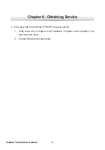
Page 20: ...Cabinet Chapter 6 Obtaining Service z z If the step down transformer TFM RT requires service 1 Verify there are no tripped circuit breakers A tripped circuit breaker is the most common issue 2 Contact Delta service personnel ...

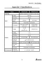
Page 21: ...able Circuit Breaker Connection Attached 10 AWG power cord Terminal Block Hardwire only Output Voltage 120 Vac or 208 120 Vac 208 120 Vac Voltage Regulation 3 Frequency 60 Hz Power Max 5kVA 5K Watts 10kVA 10K Watts Harmonic Distortion 3 full linear load Efficiency 95 full linear load 95 full linear load Waveform Type True Sine Wave Protection Resettable Circuit Breaker Environmental Operating Temp...

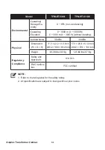
Page 22: ...ithout derating Audible Noise 55 dBA 60 dBA Physical Dimensions W D H 17 3 22 2 3 5 inch 440 2 565 88 2 mm 17 3 28 6 5 12 inch 440 2 726 130 mm Weight 85 98 Ibs 39 Kg 125 66 Ibs 57 Kg Regulatory Compliance Safety and Approvals UL CUL EMC Verifica tion FCC certified NOTE 1 Refer to the rating label for the safety rating 2 All specifications are subject to change without prior notice ...

Page 23: ...istible force i e war fire natural disaster etc and this warranty also expressly excludes all incidental and consequential damages Maintenance service for a fee is provided for any damage out of the warranty period If any maintenance is required please directly contact the supplier or Seller WARNING The individual user should take care to determine prior to use whether the environment and the load...

Page 24: ......

Page 25: ......

Page 26: ......

Page 27: ...ill VIC 3168 Australia T 61 3 9543 3720 E ups australia deltaww com Delta Electronics Korea Inc 1511 Byucksan Digital Valley 6 cha Gasan dong Geumcheon gu Seoul Korea 153 704 T 82 2 515 5303 E ups south korea deltaww com Delta Electronics Int l Singapore Pte Ltd 4 Kaki Bukit Ave 1 05 04 Singapore 417939 T 65 6747 5155 E ups singapore deltaww com Australia Thailand South Korea Singapore Delta Elect...

Page 28: ...5013274401 ...

Reviews: