background image

1. Introduction 

This series of product is a new generation of multifunctional standalone access control. It adopts new ARM core
32-bit microprocessor design, which is powerful, stable and reliable. It includes reader mode and standalone
access  control  mode  etc..  It’s  widely  applied  to  different occasions,  such  as  offices,residential  communities,
villa,bank and prison etc..

2. Features

Read 125KHz EM Card 

Operate by infrared remote control

Contains reader mode, the transmission format could be adjusted by users.

Support admin add card, admin delete card and setting card

10,000 card users

The unlocking signal adopts NO,NC,COM output of relay

3. Technical Specifications

Operating Voltage: DC 12-24V 

Standby Current: ≤35mA

Operation Current: ≤100mA

Operating Temperature: -20℃~60℃

Operating Humidity: 0%~95%

Maximum Rated Current

:≤

1A


Door Relay Time:0

99s

adjustable

Dimension: 120*56*20mm


4. Installation 

Remove the back cover from the keypad using the supplied special screw driver

Drill 2 holes on the wall for the self tapping screws and dig a hole for the cable

Put the supplied rubber bungs into the two holes

Fix the back cover firmly on the wall with 2 self tapping screws

Thread the cable through the cable hole

Attach the keypad to the back cover. (See the figure below)

Summary of Contents for ATLO-RM-822

Page 1: ...Large Capacity Access Control Proximity Card Reader ...

Page 2: ... admin delete card and setting card 10 000 card users The unlocking signal adopts NO NC COM output of relay 3 Technical Specifications Operating Voltage DC 12 24V Standby Current 35mA Operation Current 100mA Operating Temperature 20 60 Operating Humidity 0 95 Maximum Rated Current 1A Door Relay Time 0 99s adjustable Dimension 120 56 20mm 4 Installation Remove the back cover from the keypad using t...

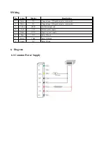
Page 3: ...s reader mode 2 White D1 Wiegand input Wiegand output as reader mode 3 Yellow OPEN Exit button input end 4 Red 12V Positive power supply 5 Black GND Negative power supply 6 Blue NO Relay NO end 7 Purple COM Relay COM end 8 Orange NC Relay NC end 6 Diagram 6 1 Common Power Supply ...

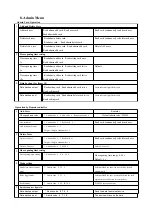
Page 4: ...ht Indication Operation Status Light indicator Buzzer Stand by Red Operation successful Green Beep Operation failed Beep Beep Beep Admin card enter programming Beep Beep Admin card exit programming Beep Press key Beep Data backup Green indicator flash slowly ...

Page 5: ...d setting card Green indicator light flash slowly Operation by Remote controller 1 Add Users Remarks Change admin code Admin code 0 New code Repeat new code Default admin code 999999 Add card user Admin code 1 Read card Read card continuously to add card user Add card number user Admin code 1 8 digits 10 digits card number 2 Delete Users Delete card user Admin code 2 Read card or 8 digits 10 digit...

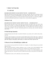
Page 6: ...once the indicator light turns red it means you have exited the delete user programming 10 Data Backup Operation Example Backup the data of machine A to machine B Machine A uses admin card of A machine B uses admin card of B The green wire and white wire of machine A connects with the green wire and white wire of machine B correspondingly set B for receiving mode at first then set A for sending mo...

Reviews: