Chapter 11 Description of Parameter Settings
|
C200 Series
11-114
x (Pr.08-04 %).
Too large integral value will make the slow response due to sudden load change. In this way, it
may cause motor stall or machine damage.
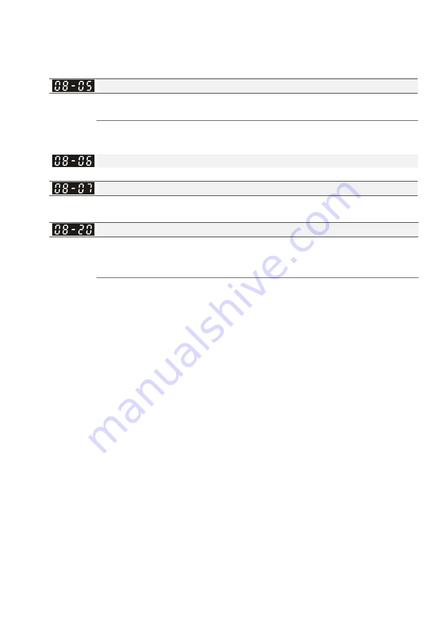
PID Output Frequency Limit
Factory
Setting:100.0
Settings 0.0~110.0%
This parameter defines the percentage of output frequency limit during the PID control. The formula
is Output Frequency Limit = Maximum Output Frequency (Pr.01-00) X Pr.08-05 %.
Reserved
PID Delay Time
Factory Setting: 0.0
Settings 0.0~35.0 sec
PID Mode Selection
Factory Setting: 0
Settings 0: Serial connection
1: Parallel connection
Pr.08-07 determines the primary low pass filter time when in PID control. Setting a large time
constant may slow down the response rate of drive.
Output frequency of PID control will filter by primary low pass function. This function could filtering
a mix frequencies. A long primary low pass time means filter degree is high and vice versa.
Inappropriate setting of delay time may cause system error.
PI Control: controlled by the P action only, and thus, the deviation cannot be eliminated entirely. To
eliminate residual deviations, the P + I control will generally be utilized. And when the PI control is
utilized, it could eliminate the deviation incurred by the targeted value changes and the constant
external interferences. However, if the I action is excessively powerful, it will delay the responding
toward the swift variation. The P action could be used solely on the loading system that
possesses the integral components.
PD Control: when deviation occurred, the system will immediately generate some operation load
that is greater than the load generated single handedly by the D action to restrain the increment of
the deviation. If the deviation is small, the effectiveness of the P action will be decreasing as well.
The control objects include occasions with integral component loads, which are controlled by the
P action only, and sometimes, if the integral component is functioning, the whole system will be
vibrating. On such occasions, in order to make the P action’s vibration subsiding and the system
stabilizing, the PD control could be utilized. In other words, this control is good for use with
loadings of no brake functions over the processes.
PID Control: Utilize the I action to eliminate the deviation and the D action to restrain the vibration,
thereafter, combine with the P action to construct the PID control. Use of the PID method could
obtain a control process with no deviations, high accuracies and a stable system.
Serial
connection
Call 1(800)985-6929 for Sales
deltaacdrives.com
sales@deltaacdrives.com
Call 1(800)985-6929 for Sales
deltaacdrives.com
sales@deltaacdrives.com


