Chapter 14 PLC Function
|
C200 Series
14-61
API
240~
246
D
OR
※
S1
S2
OR Compare
※
Bit Devices
Word Devices
X Y M K H KnX
KnY KnM T
C
D
S
1
*
*
*
*
*
*
*
*
S
2
*
*
*
*
*
*
*
*
Operands:
※
: =, >, <, <>,
≦
,
≧
Please refer to the specifications of each model for the
range of operands.
16-bit command (5 STEPS)
OR
※
ZRSTP
32-bit command (9 STEPS)
DOR
※
-
-
-
Flag signal: none
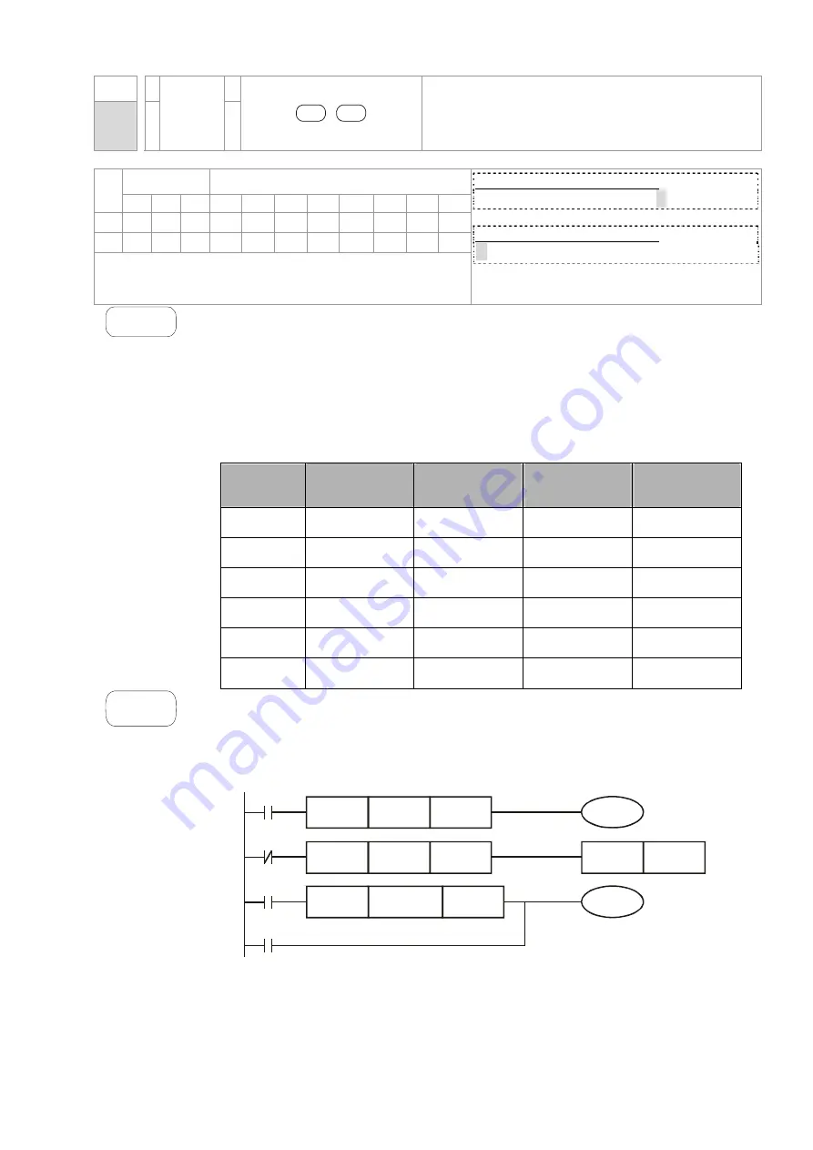
Explanation
1.
S
1
: Data source device 1
S
2
: Data source device 2
2. This instruction compares the content in
S
1
and
S
2
. Take API240 (OR=) for
example, if the result is “=”, the continuity of the instruction is enabled. If the
result is “
≠
”, the continuity of the instruction is disabled.
3. OR
(
※
:
※
=, >, <, <>,
≤
,
≥
) is an comparison instruction used on parallel
contacts.
API No.
16 -bit
instruction
32 -bit
instruction
Continuity
condition
No-continuity
condition
232
AND
=
D
AND
=
S
1
=
S
2
S
1
≠
S
2
233
AND
>
D
AND
>
S
1
>
S
2
S
1
≦
S
2
234
AND
<
D
AND
<
S
1
<
S
2
S
1
≧
S
2
236
AND
<>
D
AND
<>
S
1
≠
S
2
S
1
=
S
2
237
AND
<=
D
AND
<=
S
1
≦
S
2
S
1
>
S
2
238
AND
>=
D
AND
>=
S
1
≧
S
2
S
1
<
S
2
Example
1. When X1 = On and the present value of C10 = K200, Y0 = On.
2. When X1 = Off and the content in D0
≠
K-10, Y11= On will be retained.
3. M50 will be On when X2=On and the content of 32-bit register D0(D11) <678,493
or M3= On.
AND=
K200
C10
DAND> K678493
D10
M3
Y10
AND<>
K-10
D0
SET
Y11
M50
X2
X1
X0
Call 1(800)985-6929 for Sales
deltaacdrives.com
sales@deltaacdrives.com
Call 1(800)985-6929 for Sales
deltaacdrives.com
sales@deltaacdrives.com


