Chapter 6 Control Terminals
|
C200 Series
6-4
Terminals
Terminal Function
Factory Setting (NPN mode)
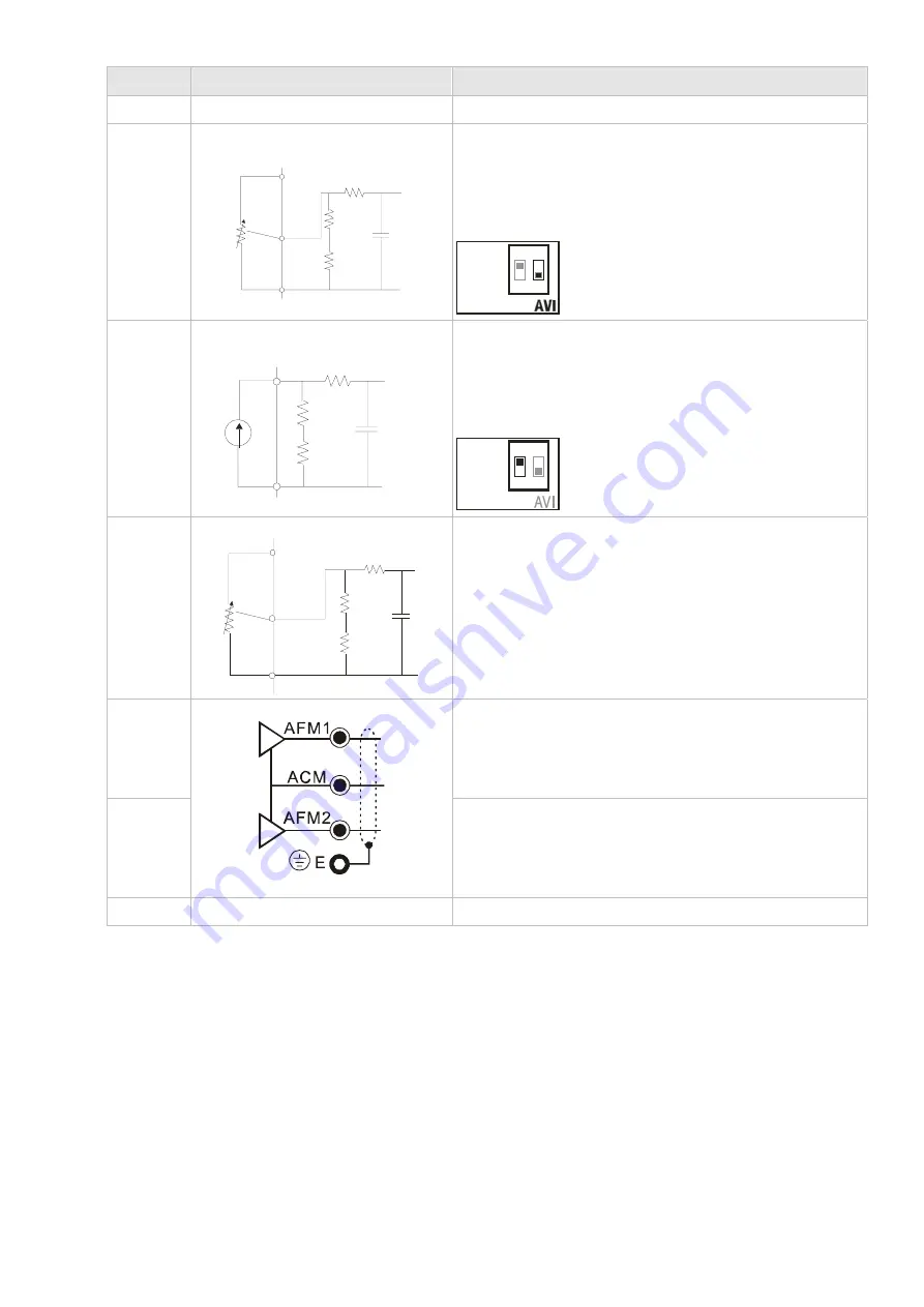
+10V
Potentiometer power supply
Analog frequency setting: +10Vdc 20mA
AVI
Analog voltage input
ACM
AVI
+10V AVI circuit
internal circuit
Impedance: 20k
Ω
Range: 0~10V/0~20mA/ 4~20mA(Pr.03-38)
=0~Max. Output Frequency (Pr.01-00)
AVI switch, factory setting is 0~10V
ACI
1
ON
2
0-20mA
4-20mA
0-10V
ACI
Analog current input
ACM
ACI
ACI circuit
internal circuit
Impedance: 500
Ω
Range: 4~20mA/0~10V/0~20mA(Pr.03-39)
=0~Max. Output Frequency (Pr.01-00)
ACI Switch, factory setting is 4~20mA
ACI
1
ON
2
0-20mA
4-20mA
0-10V
AUI
Auxiliary analog voltage input
ACM
AUI
+10
AUI circuit
internal circuit
Impedance: 20k
Ω
Range: -10~+10VDC=0 ~ Max. Output
Frequency(Pr.01-00)
AFM1
Impedance: 100k
Ω
(voltage output)
Output current: 2mA max
Resolution: 0~10V corresponds to Max. operation
frequency
Range: 0~10V
AFM2
Impedance: 100
Ω
(current output)
Output current: 20mA max
Resolution: 0~20mA corresponds to Max. operation
frequency
Range: 0~20mA, 4~20mA
ACM
Analog Signal Common
Common for analog terminals
NOTE: Wire size of analog control signals: 18 AWG (0.75 mm
2
) with shielded wire
Analog input terminals (AVI, ACI, AUI, ACM)
;
Analog input signals are easily affected by external noise. Use shielded wiring and keep it as
short as possible (<20m) with proper grounding. If the noise is inductive, connecting the shield to
terminal ACM can bring improvement.
;
If the analog input signals are affected by noise from the AC motor drive, please connect a
capacitor and ferrite core as indicated in the following diagram.
Call 1(800)985-6929 for Sales
deltaacdrives.com
sales@deltaacdrives.com
Call 1(800)985-6929 for Sales
deltaacdrives.com
sales@deltaacdrives.com


