background image

EtherCAT Communication Card: CMC-EC01


CMC-EC01 Operation Manual


2


Table of Content


1


Introduction ....................................................................................................................... 3


1.1 

EtherCAT Description ........................................................................................................... 3 

1.2 

Functionality .......................................................................................................................... 3 

2


Product Profile and Outline ............................................................................................. 4


2.1 

Dimension ............................................................................................................................. 4 

2.2 

Parts ...................................................................................................................................... 4 

2.3 

LED indicator ........................................................................................................................ 5 

2.4 

RJ-45 PIN Definition ............................................................................................................. 5 

3


Installation and Wiring ..................................................................................................... 6


3.1 

How to Install ........................................................................................................................ 6 

3.2 

How to Disconnect ................................................................................................................ 6 

3.3 

Wiring .................................................................................................................................... 7 

4


VFD-C2000 Drive Configuration ...................................................................................... 8


5


EtherCAT List and Description of supported Index ....................................................... 9


5.1 

Index related to the state machine ........................................................................................ 9 

5.2 

Index related to the control mode ....................................................................................... 10 

5.3 

Index related to the speed .................................................................................................. 10 

5.4 

Index Related to Disconnections ......................................................................................... 11 

6


Configuring the Connection with the Beckhoff PLC.................................................... 13


6.1 

Basic Configuration ............................................................................................................. 13 

6.2 

Speed Mode Demo ............................................................................................................. 17 


Summary of Contents for CMC-EC01

Page 1: ...CMC EC01 EtherCAT Communication Card Operation Manual 20170720 ...

Page 2: ...rical and electronic product For the safety of operator and the mechanical equipment please allow professional electrical mechanics to do the trial run and adjust parameters for you Should there be any questions please consult your local Delta distributors Our professional staff will be happy to help you Please read this operation manual thoroughly and follow the instructions in case damage on the...

Page 3: ...efinition 5 3 Installation and Wiring 6 3 1 How to Install 6 3 2 How to Disconnect 6 3 3 Wiring 7 4 VFD C2000 Drive Configuration 8 5 EtherCAT List and Description of supported Index 9 5 1 Index related to the state machine 9 5 2 Index related to the control mode 10 5 3 Index related to the speed 10 5 4 Index Related to Disconnections 11 6 Configuring the Connection with the Beckhoff PLC 13 6 1 Ba...

Page 4: ...000 support EtherCAT communication card from v2 02 please make sure if the drive firmware is supported or not Specification Item Specifications Connection RJ 45 Ports 2 Port Interface IEEE802 3 IEEE802 3u Cable Category 5e shielding 100 M Speed 10 100 Mbps Auto Defect Protocol EtherCAT Environment Item Specifications Nosie Immunity ESD IEC 61800 5 1 IEC 6100 4 2 EFT IEC 61800 5 1 IEC 6100 4 4 Surg...

Page 5: ...e and Outline 2 1 Dimension Unit mm inch 2 2 Parts 1 Screw fixing hole 7 IN LINK indicator 2 Positioning hole 8 Fool proof groove 3 RUN indicator 9 RJ 45 connection port 4 ERR indicator 10 RJ 45 connection port 5 POWER indicator 11 AC motor drive connection port 6 OUT LINK indicator ...

Page 6: ...r on off 200ms Status witch error on200ms off1000ms Timeout on 200ms twice off1000ms Off No error IN LINK Green On Network connected Blink Network in operation Off Network not connected OUT LINK Green On Network connected Blink Network in operation Off Network not connected 2 4 RJ 45 PIN Definition RJ 45 Sketch No Signal Definition 1 Tx Positive pole for data transmission 2 Tx Negative pole for da...

Page 7: ...les with the PCB see Figure 2 Crew up at torque 6 8 kg cm 5 2 6 9 lb in 0 59 0 78 Nm after the PCB is clipped with the holes see Figure3 Figure1 Figure 2 Figure 3 3 2 How to Disconnect How to disconnect CMC EIP01 from VFD C2000 Switch off the power of VFD C2000 Open the front cover of VFD C2000 Remove the two screws see Figure 4 Twist open the card clip and insert the slot type screwdriver to the ...

Page 8: ...e correct wiring method shown below After hardware installation is complete turn on the power and look at parameter P9 60 The value displayed should be 6 and the word EtherCAT should also be displayed If not please check the version of the inverter and whether the card has been correctly connected C2000 of version v2 02 or above may support CMC EC01 ...

Page 9: ... C2000 product description file is CMC EC01 with C2000 xml and this file can be obtained from Delta s website 2 To have C2000 calculate correctly the output frequency by sending a target speed command please enter motor pole number parameter based on the motor type set at Pr 05 33 For example set Pr 05 04 if it is asynchronous motor or set Pr 05 37 if it is synchronous motor Parameter Value Displa...

Page 10: ...ntrol follow DS402 protocol definitions These definitions are described in detail in the following sections 5 1 Index related to the state machine In the DS402 definition state machine state changes are conducted via the Index 6040 control word bit0 3 and 7 The current state of the state machine is shown in the 6041 status word bit0 6 Therefore corresponding bit definitions are as follows Index 60...

Page 11: ...the state machine are as shown below 5 2 Index related to the control mode 5 3 Index related to the speed When Index 6060 2 and the state machine is in the Operation Enable state the speed of the drive can be controlled The indexes and controls currently provided by the C2000 in speed mode are listed below ...

Page 12: ...communications connection is confirmed to be re established and Bit 7 of 6040 changes from 0 to 1 the error code will be cleared and the state machine will enter the Switch on Disable state When 2 is selected for 6007 and a disconnection occurs the CANopen state will change to Switch On Disable ECto will be displayed and the stop operation will be triggered according to the index 605A settings Whe...

Page 13: ...he state machine is in the Quick Stop state stopping of the system will be conducted in accordance with the settings of Index 605A When the state machine is in the Switch On Disable state stopping of the system will be conducted in accordance with the settings of Index 605C ...

Page 14: ...e using TwinCAT V2 11 and Beckhoff PLC by EtherCAT communication with VFD C2000 Hardware configuration as following figure PC connects to Beckhoff PLC by Ethernet PLC use EtherCAT Master connects to C2000 CMC EC01 6 1 Basic Configuration Basic Configurations 1 Select automatically obtain IP address for the PC s network IP setting ...

Page 15: ...peration Manual 14 2 Place the CMC_EC01 with C2000 xml file into the corresponding folder TwinCAT Io EtherCAT Open System Manager 1 Click Choose Target System Since there are no target systems in the beginning you must first scan for target systems ...

Page 16: ...1 CMC EC01 Operation Manual 15 2 Scan via IP broadcast 3 Select PLC module and click OK Left click and select Scan Devices note that the system must be in Configuration Mode From the scan results select the EtherCAT communications option ...

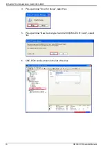
Page 17: ...mmunication Card CMC EC01 CMC EC01 Operation Manual 16 4 Pop up window Scan for boxes select Yes 5 Pop up window New device type found C2000 CMC EC01 Card select Yes 6 CMC EC01 will be shown in the list of devices ...

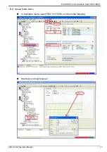
Page 18: ...EtherCAT Communication Card CMC EC01 CMC EC01 Operation Manual 17 6 2 Speed Mode Demo In Configure mode select PDO1 for TX RX and then start mapping Start test and modify speed ...

Page 19: ...2 Set Control Word 0xE state machine of drive enters to Power Enable 3 Set Control Word 0xF state machine of drive enters to Operation Enable 4 Set Control Word 0x7F allowing the drive to reach the target frequency 5 Set vl target velocity 1200 drive begins operating in reverse 6 Set Control Word 0x5F the drive stops at the current frequency ...

Reviews: