•
14
•
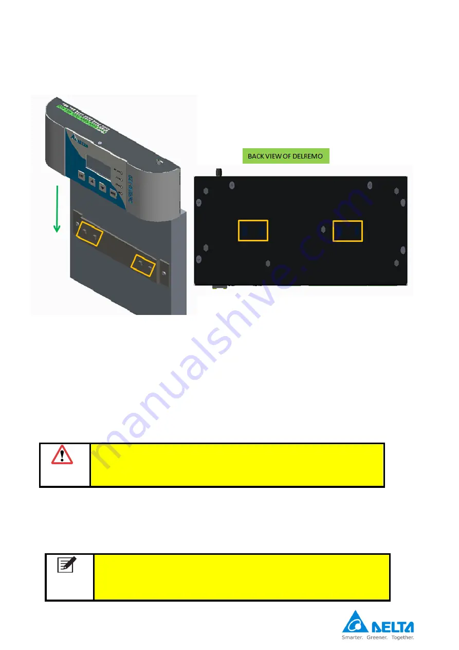
Move the DelREMO-V2.0 downwards as shown below. Note that slot represented locks
with hooks provided in wall
.
Step 4:
→
System Handling
While opening and closing the top cover of DELREMO system, special attention is required towards LCD
connector, as the top cover may damage LC
D’s harness while opening and closing.
Step 5:
→
Adapter connections
Step 6:
→
Solar Inverter Modular interconnection procedure
Modular interconnection procedure involves interconnection to various modules of the system on RS 485
daisy chain to make it functional.
WARNING
While connecting the adapter output to DelREMO System polarity
of the supply must be checked. The 24 VDC input to system must
be connected to input terminal provided only.
NOTE
MAXIMUM 30 NUMBERS OF SOLAR INVERTER MODULES CAN BE
CONNECTED OVER RS485 DAISY CHAIN OVER 1 PORT. USE PROVIDED
RS485 TERMINAL BLOCK FOR CABLE TERMINATION AT DELREMO
SYSTEM. THUS MAXIMUM 60 INVERTERS CAN BE CONNECTED OVER 2
RS485 PORTS.
Fig 3.2 DelREMO-V2.0 Wall Mounting Arrangement
Summary of Contents for DelREMO-V2.0
Page 1: ...1 User Guide Indoor DelREMO V2 0 www deltaelectronicsindia com...
Page 2: ...2...
Page 18: ...18...
Page 44: ......
Page 45: ...Recycle paper Save earth...


