7 - 2 7
7
LCD Display & Settings
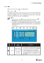
7.9.7 EMS
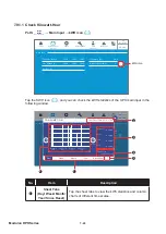
Path 1:
Tap the shortcut icon (
EMS
) on the
Main Screen
.
Path 2:
MEASUREMENT
ĺ(06
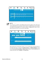
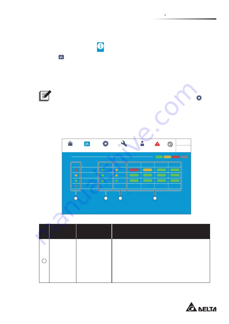
To activate the EMS function of the UPS, you have to connect the optional EMS 1000
(EnviroProbe) device(s) with the UPS; the EMS information of each device (ID #) will be
displayed on the
EMS
VFUHHQDVVKRZQLQWKH¿JXUHEHORZ3OHDVHUHIHUWRWKHWDEOHEORZ
for the descriptions of each item shown on the
EMS
screen.
NOTE:
1. The items shown on the
EMS
screen is related to the settings in the (
SETUP
ĺ
EMS Setting
; the settings can be adjusted according to your needs.
2. For installation of the optional EMS 1000 (EnviroProbe), please refer to
&RQQHFWLQJ WKH RSWLRQDO (06 (QYLUR3UREH
and the
(QYLUR3UREH
4XLFN *XLGH
attached in the package of the optional EMS 1000
(EnviroProbe).
On-Line
0
EMS0
25.4
°C
52
%
ID
1
3
6
Security 1
2
qqqqq3
qqpo4
EMS1
25.8
°C
51
%
Security 1
2
qqqqq3
qqpo4
EMS3
25.9
°C
51
%
Security 1
2
qqqqq3
qqpo4
EMS6
°C
%
S1
L2
F3
S4
EMS
UPS-1.1
SETUP
MAINTENANCE
LOG IN
Administrator
MEASUREMENT
EMS
10:15
May 25,2018
2
WARNING
Normal
Warning
Alarm
Off
Temperature
Title
Humidity
DI1
DI2
DI4
DI3
1
2
3
4
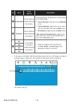
No.
Item
Color
(Status)
Descriptions
1
ID
Green (Normal)
Yellow (Warning)
Red (Alarm)
*UD\2ႇ
1. ID # represents each EMS 1000 (EnviroProbe)
device which is connected and set as '
Enable
'.
2. Shows the integrated status of each EMS
1000 (EnviroProbe) device. The integrated
status is determined by the most severe status
among
Temperature
(°C),
Humidity
(%) and
DI1 ~ DI4
.
Summary of Contents for DPH-300K
Page 8: ......
Page 14: ......
Page 60: ......
Page 76: ......
Page 227: ...8 1 8 Optional Accessories 8 Optional Accessories ...
Page 230: ......
Page 231: ...9 1 9 Maintenance Maintenance ...
Page 233: ...A1 1 Appendix 1 7HFKQLFDO 6SHFL FDWLRQV Technical 6SHFL FDWLRQV A1 A1 ...
Page 236: ......
Page 237: ...A2 1 Appendix 2 Warranty Warranty A2 A2 ...
Page 240: ... ...

