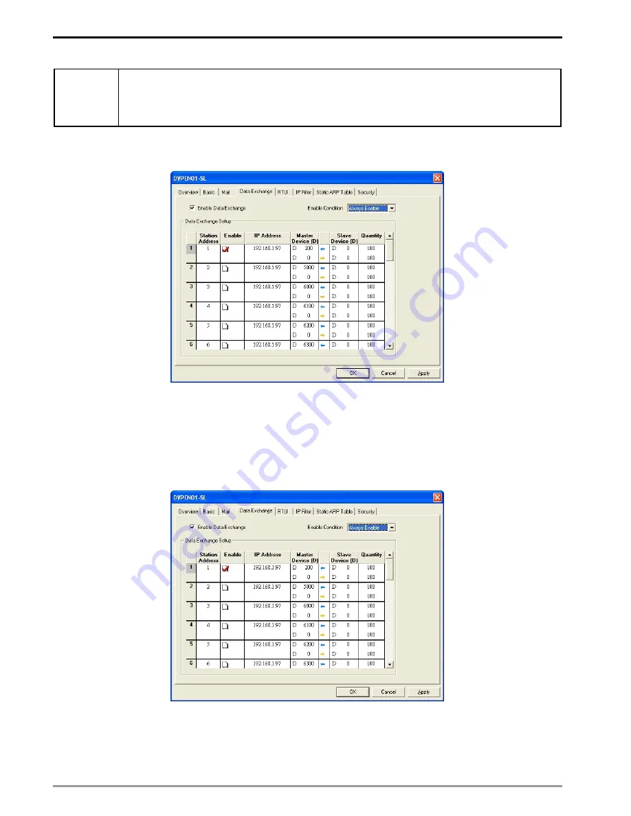
Ethernet Communication Module DVPEN01-SL
DVP-PLC Operation Manual
50
Network
environment
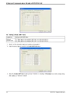
(1) Adopt a static IP address.
(2) IP address of PLC_A: 192.168.1.99
(3) IP address of PLC_B: 192.168.1.97
(4) Update from PLC_A to PLC_B and PLC_B to PLC_A.
1. See 6.1 for how to set the communication.
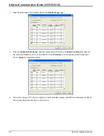
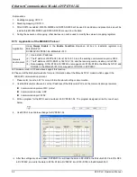
2. Open the setup page of PLC_A and switch to the
Data Exchange
page.
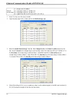
3. Select the
Enable Data Exchange
checkbox. Select
Always Enable
in the
Enable Condition
drop-down list
box. Check the
Enable
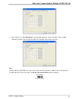
cell corresponding to station address 1.Enter the IP address of PLC_B “192.168.1.97” in
the
IP Address
cell corresponding to station address 1, select D200 and D0 in the
Master Device
cell
corresponding to station address 1, select D0 and D0 in the
Slave Device
cell corresponding to station address
1, and select 100 and 100 in the
Quantity
cell corresponding to station address 1.
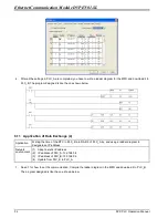
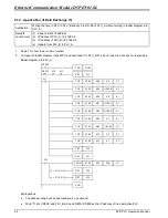
4. After all the settings in PLC_A are completed, you have to write a ladder diagram for the MPU and download it to
PLC_B. The program designed is like the one shown below.


