Fig.
25.
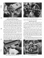
sure bar up or down by turning the adjusting nuts with
a wrench until it just touches the surface of the piece
of wood. When making this adjustment be sure to
turn each adjusting nut the same amount.
Place the rubber pressure pad, special steel washer
and the special hexagon nut on each of the studs. To
apply pressure hold the adjusting nut in position with
a wrench so it will not turn with one hand and tighten
the special hexagon nut with the other hand until the
desired amount of pressure is obtained. Be sure to
apply the same amount of pressure on each side of the
bar when making this setting. Refer to Fig. 22.
Installation and Adjustment of New Gears
The cutter head with bearings, housing, and knife
blades must be removed first, see Figure 38. Drain oil
Fig.
26.
12
Fig.
27.
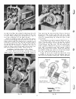
from gear box by removing pipe plug as shown in
Figure 20. Then remove gear box and cover plate.
See Figure 1 1 . It is also necessary to remove the roller
chain, by disassembling the connective link in each
chain length.
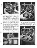
The sprocket gear shaft assembly PLR-342-S, con
sists of the gear shaft, clutch, thrust washer, sprocket
worm gear, oil slinger, clutch sprocket, key spacer,
thrust bearing, and snap ring. The intermediate gear
shaft assembly PLR-343-S consists of intermediate
gear shaft, intermediate gear, ball bearing, support
block, snap ring, and set screws. These two shafts are
assembled at the factory, each as a unit, and are shipped
as a unit, under PLR numbers given above.
Figure 25 shows how these two shafts are to be
assembled in the gear box. The intermediate gear will
mesh with the sprocket worm gear when in position,
5-29-51
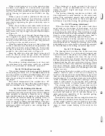
BACKLASH SETTING
FOR
WORM GEAR DRIVE
Fig.
28.
Summary of Contents for Milwaukee PM-1738
Page 1: ...13x5 INCH DELTA MILWAUKEE 7 7 1M rJ6fiUAKJ PM 1738 ...
Page 2: ......
Page 27: ......
Page 28: ......


