background image

SP-2653  STR AIGHT  KEY 

MOTOR

""\/

-�:C·--

LEG  CASTING  PLR-8 

PANEL 

,ceo' 

LEG  CASTING 

PLR-8 

SCREW 

SIDE 

PLR-IO 

MACH.  SCREW 

(l6)PLR-73 

Convenient  location  of  the  ralsmg  and  lowering 

mechanism of  the  table on  the left side  of  the  machine 
permits  the  table  to  be  raised  or  lowered  in  a  mini­

mum  amount  of  effort  and  time. 

Conveniently  mounting  the  finished  size  scale  on 

the left side of the machine eliminates  any unnecessary 
bending and eye strain on the part of the operator when 
making  the  table  setting  required.  This  scale  has  been 

made  very  legible and  is  accurately  graduated. 

To  compensate  for  wear  of  the  table  sliding  in 

relation  to  the  right  and  left-hand  columns,  we  have 
incorporated into  this  machine  steel  table  gibs to main­
tain  its  original  tight  sliding  fit  at  all  times.  These 
gibs  can  be  drawn  up  by  means  of  three  adjusting 
screws  on  each  side  of  the  table  casting. 

The  unique  clutch  mechanism  enables  the  operator 

to  stop  and  start  the  feed  instantly  without  shutting 
off  the  motor. 

The  chip  breaker  and  the  pressure  bar  completely 

guard the cutter head and feed rolls to insure maximum 

protection  to  the  operator  and  can  be  easily  removed 

for  accessibility  to  these  parts.  In  addition,  the  safety 
type chip breaker design prevents the chips from being 
thrown  on  the  operating  side  of  the  machine.  It  is 
also  made  long  enough  to  prevent  the  fingers  of  the 
operator  from  coming  in  contact  with  the  revolving 
knife  blades  in  the  cutter  head  if  he  should  ever  grasp 
it  from  the  operating  side  of  the  machine. 

The  serrated  in-feed  and  the  smooth  out-feed  rolls 

are  provided  with  compression  springs  so  they  can 
be  readily  adjusted  for  planing  any  type  of  stock. 

Positive  stops  are  provided  to  eliminate  the  table 

from  striking  the  revolving  knife  blades  in  the  cutter 
head  when  adjusting  it  for  planing  thin  material. 

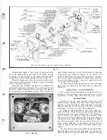
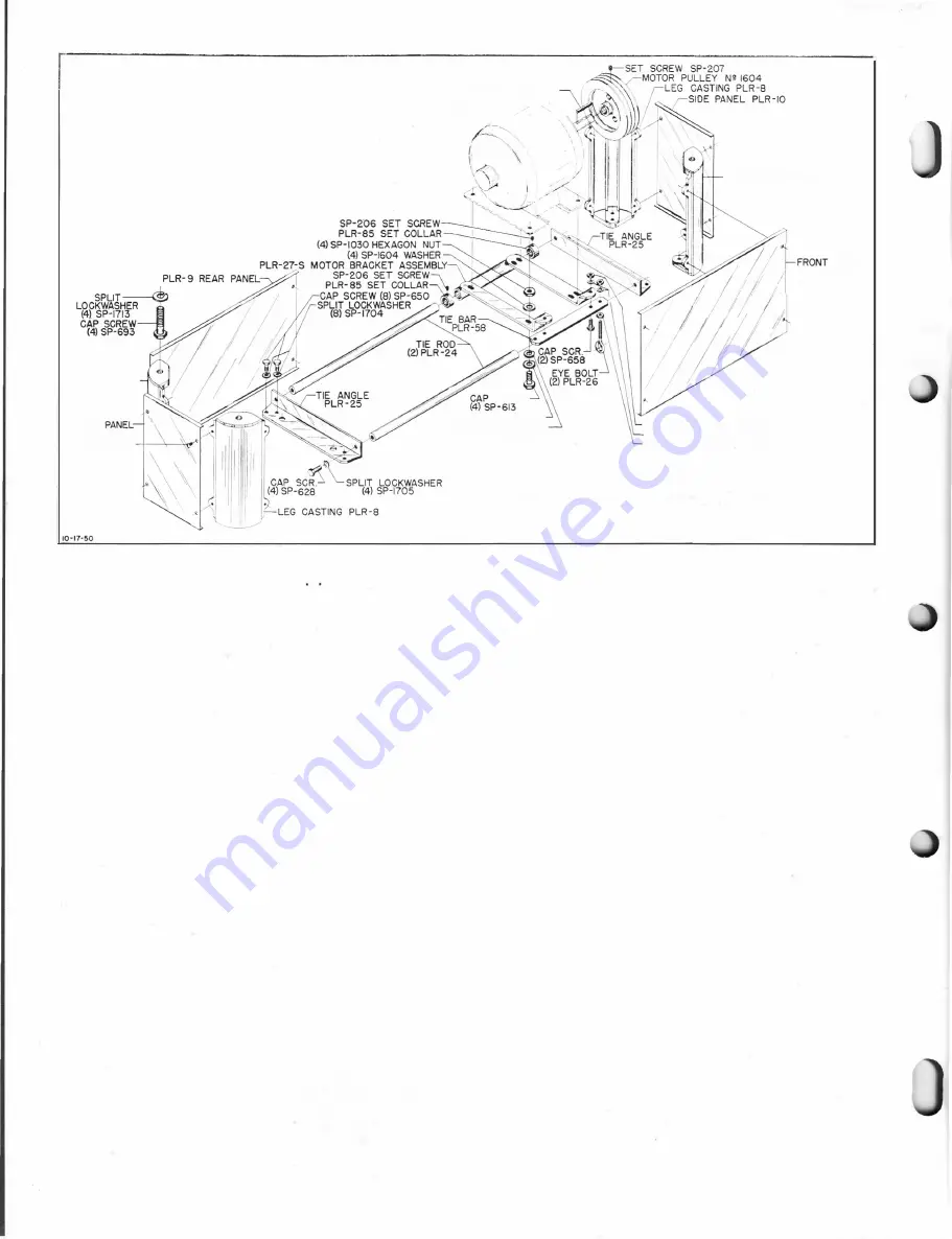
The  motor  bracket  of  the  sub-base  assembly  has 

(4) SP-1604  WASHER 

SPLIT  LOCKWASHER 

(4) SP-1703 

HEXAGON  NUT  (4)  SP-1207 

SPUT  LOCKWASHER  (4)  SP-1709 

H E XAGON  NUT  (2)  SP-1207 

SUB- BASE  AND  MOTOR  BRACKET  ASSEMBLY 

Fig. 

2. 

holes  provided  in  it  to  receive  No.  224  and  No.  225 

standard  NEMA  frame  motors. 

The  feed  mechanism  is  fully  enclosed  within  the 

gear  box.  The  positive  powerful  drive  consists  of  a 

continuous  anti-friction  roller  chain  which  connect 
solid  steel  sprockets.  One  chain  assembly  is  driven  by 
a  double  worm  gear  reduction  drive  which  in  turn  is 

driven  by  the  cutter  head.  The  cutter  head  is  driven 

from the motor by means of a matched set of 3 V -belts. 

POWER,  SPEED  AND  FEED 

Use  a  3  hp  motor for  this machine.  We  have  avail­

able  a  3  hp,  single  phase  motor  and  a  3  hp,  three 
phase  motor  according  to  the  customer's  choice.  We 
recommend  using  the three  phase  motor  whenever  the 
power  is  available. 

The  correct  motor  speed  with  60  cycle  power  is 

1725  rpm,  which  will  run  the  cutter  head  at  4200  rpm. 
This  speed  is  obtained with a 3  23/64"  diameter  cutter 

head  pulley  in  conjunction  with  the  7"  motor  pulley 

No.  1604  furnished  as  standard  equipment. 

For  50 and  25  cycle  current,  use  a  1 425  rpm  motor 

to  run  the  cutter  head  at  4200  rpm.  This  speed  is 

obtained  with  a  3  23/64"  diameter cutter  head  pulley 

furnished  as  standard  equipment  and  an  8Yz"  motor 

pulley  No.  22-105  which  is  available  and  can  be  pur­

chased  extra. 

The  cutter  head  running  at  4200  rpm  takes  12,600 

cuts  per  minute.  The  feed  rate  is  14  lineal  feet  per 
minute  and  75  cuts  are  taken  on  each  inch  of  ma­
terial feed to produce a veneer finish which is so smooth 

that all subsequent sanding is held down to a minimum. 

All  motor  pulleys  furnished  for  this  machine  have 

a  1 "  bore  and  a 

Y4" 

keyway.  They  fit any  of  tl;!e  Delta 

motors  recommended  for  this  machine.  Consult  your 

Delta  dealer  for  the  correct  motor  to  meet  your  needs. 

Summary of Contents for Milwaukee PM-1738

Page 1: ...13x5 INCH DELTA MILWAUKEE 7 7 1M rJ6fiUAKJ PM 1738 ...

Page 2: ......

Page 3: ...176 V Belt and No 22 105 8Yz diameter pulley The motor magnetic starters and electrical connec tion from the starter to the motor are available and can be purchased additional according to the cus tomer s choice Accessories which may be purchased as additional equipment are 7 motor pulley No 1604 sub base including the motor mounting bracket No 22 102 matched set of 3 high speed steel knife blades...

Page 4: ...king the revolving knife blades in the cutter head when adjusting it for planing thin material The motor bracket of the sub base assembly has 4 SP 1604 WASHER SPLIT LOCKWASHER 4 SP 1703 HEXAGON NUT 4 SP 1207 SPUT LOCKWASHER 4 SP 1709 H E XAGON NUT 2 SP 1207 SUB BASE AND MOTOR BRACKET ASSEMBLY Fig 2 2 holes provided in it to receive No 224 and No 225 standard NEMA frame motors The feed mechanism is...

Page 5: ...R WASHER 2 HDP 122 I PLR 96 HELICAL GEAR I SP 5072 ROLL PIN TABLE R OLLER 2 PLR 46 ADJUSTING NUT SUPPORT PLR II I ADJUSTING NUT PLR 12 SPLIT LOCKWASHER 2 SP 1704 CAP SCREW 2 SP 642 TABLE ELEVATING SCREW PLR 18 I I THRUST BALL BEARING PLR 134 TABLE ROLLER WITH BEARINGS 2 PLR 47 A SP 3 SPLIT LOCKWASHER 4 SP 1713 CAP SCREW 4 SP 691 LOAOING SPRING SR 250 ROLL PIN SP 2712 FISER WASHER 3 L TA 462 PINION...

Page 6: ...uilt to stand on any level surface STARTERS AND ELECTRICAL CONNECTIONS The magnetic starters available with start and stop reset push buttons are conveniently mounted in the left hand column as shown in Fig 4 so they become an integral part of the machine Mounting the starters in this manner provides for a permanent safe connec tion and permits the machine to be easily wired from any convenient po...

Page 7: ...n the sub base assembly and work through these openings on the right side of the machine To line up the pulleys accurately take an ordinary plumb and place the cord in one of the V belts grooves in the pulley on the cutter head Shift the motor pulley on its shaft until the same groove of the motor shaft pulley and the cutter head puliey have been lined up with the plumb Then tighten the set screw ...

Page 8: ...ted for their entire life 6 Fig 9 Raising Mechanism View from Beneath Base Casting The raising gears and elevating screws of the table have been generously greased at the factory when assembled The gears and elevating screws of the raising mechanism are readily accessible for additional lubrication when required Refer to Figs 9 and 10 The four guide blocks which carry the serrated in feed and smoo...

Page 9: ...echanism a slinger type construc tion which always carries a constant supply of the oil to the gears and bearings To drain this oil from the gear case remove the pipe plug from the bottom of the gear case as shown in Figure 20 OPERATING ADJUSTMENTS The controls and adjustments described below are important for accuracy and convenience in various operations Follow these directions for best results ...

Page 10: ...machined surfaces which ride in relation to a machine surface of each column Between each side of the table casting and the columns we have incorporated a steel gib to take up all play between these machined surfaces This adjustment has been carefully made at the factory but we suggest checking the table to see if any play does exist If the table cannot be raised or iowered easily or if the table ...

Page 11: ...cut on a piece of scrap stock then measure the thickness of the stock accurately and adjust the scale This can be accom plished by loosening the two round head machine screws which attach it to the left hand column and set it so the pointer indicates a reading exactly equal to the thickness of the stock planed Refer to Fig 18 The design of this machine is such that the maxi mum cut which can be ta...

Page 12: ...eplace these chains proceed as follows _ Drain the gear box of oil see Figure 20 Remove the shifter assembly of the clutch mechanism as described under Clutch Mechanism Remove the four special slotted head nuts and the six fillister head cap screws which secure the gear box casting to the left hand column The fiber gasket between the machined surfaces of the gear box and left hand column casting w...

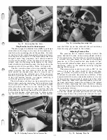
Page 13: ...d will not be nicked or hit y the chip breaker while removing it After remov mg the four fillester head cap screws the chip breaker Fig 22 Adjusting Pressure Pad on Pressure Bar 11 Fig 23 Assembling Connecting Link must be lifted up on one side and slid out and away from the stop pin located in the column Adjusting Pressure Bar The pressure bar is located directly behind the cutter head and it rid...

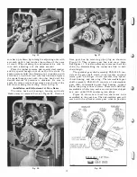
Page 14: ...be removed first see Figure 38 Drain oil Fig 26 12 Fig 27 from gear box by removing pipe plug as shown in Figure 20 Then remove gear box and cover plate See Figure 1 1 It is also necessary to remove the roller chain by disassembling the connective link in each chain length The sprocket gear shaft assembly PLR 342 S con sists of the gear shaft clutch thrust washer sprocket worm gear oil slinger clu...

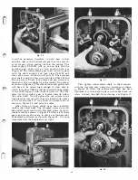
Page 15: ... to the shaft support with three cap screws The lock plate for the sprocket gear is located directly below the cutter head Do not tighten the cap screws in the lock plates at this time To raise the infeed roller place a 2 x 4 wood block x 4 long under the infeed roller as shown in Figure 30 and raise the table After these two gear shafts have been installed replace the cutter head The Hi speed wor...

Page 16: ...this clearance be more than 010 the oil slinger disc will have to be bent towards the gear on the inter mediate shaft This can be don by rapping or bending the disc until the correct clearance has been obtained A clearance of 010 or less must be held to insure the proper lubrication of the gears Use a good grade of SAE 140 steam cylinder oil only It is available in one gallon containers at the fac...

Page 17: ... this operation as many times as necessary until the throat bar is held lightly against the knife blade Do Fig 36 Checking Height of Knife Blade 15 Fig 37 Adjusting Height of Knife Blade not turn each adjusting screw out the full amount taking one at a time because all nine screws must be turned out gradually to insure the same amount of pressure across the entire length of the knife blade To adju...

Page 18: ...r when the bearings of the cutter head need replacement re move the entire cutter head with bearings housings and knife blades from the machine and return it to the factory We suggest placing masking tape or other protective cover over the edge of each knife blade in the cutter head before attempting to remove it from the machine To remove the cutter head with bearings housings and knife blades pr...

Page 19: ...he machine This roll is also held down by means of compression springs to give it the required pressure for the stock being planed Refer to Fig 40 17 It can be noticed that the table of the planer has two cylindrical rollers idlers which can be adjusted for the type of lumber that passes over the table For smooth lumber these rolls are best set at 005 above the table surface and for rough lumber t...

Page 20: ...sults we suggest taking light cuts of 1 32 only If successive light cuts are necessary turn Fig 42 Front View Planing Heavy Stock 18 Fig 43 Rear View Planing Heavy Stock the thin stock over and plane alternate surfaces until the desired thickness is obtained Planing Thin Stock Planing thin stock on the Delta planer enables the operator to produce a nice smooth even surface on the material as thin ...

Page 21: ...ly smooth with an even surface to the desired thickness Place a follower block of the same thickness square ly with the piece before it so their edges match This will prevent chipped or splintered edges Be sure to hold the follower block against the piece before it tight and squarely in line with it until the serrated in feed roll starts to push the follower block into the machine Refer to Fig 46 ...

Page 22: ...es This attachment is easily mounted to the top of the planer It has an adjustable stud at the front to obtain the correct height and angle of its cup type grinding wheel The positive indexing mechanism included with this attachment is easily installed on the cutter head pUlley This mechanism permits each knife blade of the cutter head to be ground on the same angle and held firmly in position dur...

Page 23: ...x 1 Long Table 1 PLR I06 1 Retainer Ring 16 Gauge Wire Adjusting Nut Support Tapped Full Length 1 12 Thd 2 PLR I07 Special Steel Washer 72 I O 5 4 0 0 x Ys Thick Adjusting Nut 172 Oiam x 2 Lg Threaded l U 12 2 PLR I08 Oil Slinger for Hi Speed Worm Table Elev Screw 10Y i Lg Ys 8 ACME Thd 1 End 2 PLR 1 1 0 Steel Spacer for Sprocket Gear Hex Head Shoulder EoIt S U Lg Thd 18 x 2 4 PLR 1 14 Gasket for ...

Page 24: ...P 2661 SP 3303 SP 7070 No 109 No 1604 No 40S1 No 22 102 No 22 104 No 22 I OS No 22 106 No 22 107 No 22 1 13 No 22 1 14 No 22 I I S No 22 1 1 6 No 22 1 17 No 49 17S No 49 176 No 49 320 No 49 386 No 49 387 No 49 389 Support Block for Chip Breaker New Departure Ball Brg Radial Type CWC 88S0S Knife Gauge Oil Slinger Assembly Load Spring Knife Blade 2 x 11 6 x 13yP PLR 60 Set of 3 V Belts Set of 3 Matc...

Page 25: ...ed set of 3 high speed steel knife blades ball bearings and bearing hous ings and Hi Speed worm ELECTRICAL STARTERS Magnetic starters are available with start and stop reset push buttons All electrical starters available for this machine are open type without box enclosure operate on AC current and are for either single or 3 phase motors only Please specify the motor horsepower phase voltage amper...

Page 26: ...rew For use with 1 425 rpm motors only No 22 1 1 4 3 47 64 Diameter motor pul ley with three 3 grooves for A sec tion V belts 1 diameter hole for motor shaft and set screw For use with 3450 rpm motors only SHAVING HOOD The shaving hood will keep the machine and the work free and clear of chips at all times enabling the operator to see the work much better It will reduce to a mini mum the possibili...

Page 27: ......

Page 28: ......

Reviews: