5 - 2 5
5
Installation and Wiring
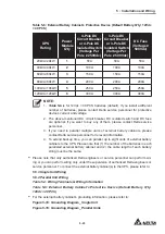
Table 5-6: External Battery Cabinet’s Protective Device (Default Battery Q’ty: 12Vdc
× 40 PCS)
UPS
Rating
Power
Module
Q’ty
4-Pole DC
Circuit Breaker
or 4-Pole DC
Isolated Switch
(Voltage Per
3ROH9GF
3-Pole DC
Circuit Breaker
or 3-Pole DC
Isolated Switch
(Voltage Per
3ROH9GF
DC Fuse
9ROWDJH
500Vdc)
20kVA/ 20kW
1
50A
50A
50A
40kVA/ 40kW
2
100A
100A
100A
60kVA/ 60kW
3
150A
150A
150A
80kVA/ 80kW
4
200A
200A
200A
100kVA/ 100kW
5
250A
250A
250A
120kVA/ 120kW
6
300A
300A
300A
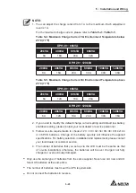
NOTE:
1.
Table 5-6
LVIRU9GFî3&6EDWWHULHVGHIDXOW,I\RXLQVWDOODGLႇHUHQW
number of batteries, please contact Delta service personnel for protective
device’s current and voltage.
2. The above-mentioned DC circuit breaker, DC isolated switch and DC fuse
are optional. If you want to buy any of them, please contact Delta service
personnel.
3. If you need to parallel multiple units of external battery cabinets, please
contact Delta service personnel for relevant information.
4. To extend backup time, you can parallel up to eight units of external battery
cabinets to the UPS. Please note that (1) the number of the batteries in each
paralleled external battery cabinet and (2) the cable length of each battery
string must be the same.
y
Please note that only authorized Delta engineers or service personnel can perform wir-
ing or you can perform wiring only under the supervision of authorized Delta engineers or
service personnel. To connect the external battery cabinet(s) to the UPS, please refer to:
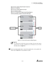
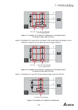
5.5.3 Single Unit Wiring
5.5.4 Parallel Unit Wiring
Table 5-3: Wiring Terminals & Wiring Information
Table 5-6: External Battery Cabinet’s Protective Device (Default Battery Q’ty:
12Vdc × 40 PCS)
y
For the external battery cabinet’s grounding information, please refer to:
Figure 5-16: Grounding Diagram_ Single Unit
Figure 5-18: Grounding Diagram_ Parallel Units
Summary of Contents for Modulon DPH series
Page 26: ......
Page 58: ......
Page 168: ......
Page 237: ...8 1 8 Optional Accessories 8 Optional Accessories...
Page 240: ......
Page 241: ...9 1 9 Maintenance Maintenance 9...
Page 243: ...A1 1 Appendix 1 7HFKQLFDO 6SHFL FDWLRQV Technical 6SHFL FDWLRQV A1 A1...
Page 246: ......
Page 247: ...A2 1 Appendix 2 Warranty Warranty A2 A2...
Page 250: ......

