7 - 3
7
LCD Display & Settings
NOTE:
1.
*
1
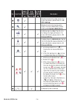
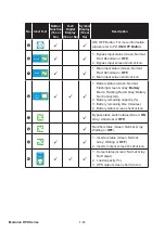
means that the
Administrator
password is needed. For password information, please
refer to
7.5 Password Entry
.
2.
*
2
means that the item will only appear on the LCD if you use the Delta lithium-ion
batteries with the optional multifunctional communication card (MFC) being installed in
the smart slot shown in
Figure 4-15
. Please contact Delta customer service if you need
more information.
3.
*
3
means that the item will only show up after you (1) use the optional battery
management system (BMS) and connect it to the BMS port shown in
Figure 4-25
. If any
question, please contact Delta service personnel.
4.
*
4
means that the item will only show up after you go to
MEASUREMENT
ĺ
BMS
and select
'
Main
' in the upper left corner of the screen.
5.
*
5
means that the item will only show up after you go to
SETUP
ĺ
BMS Setting
and select
'
Internal Resistance
' in the
Module Type
list.
6.
*
6
means that the item will only show up after you go to
SETUP
ĺ
BMS Setting
and select
'
Main
' in the
Module
list.
7. The information on the LCD screen presented in
7. LCD Display & Settings
, including
the UPS operation mode, machine number, date, time, total number of alarms, load
(%), battery remaining time, user login or administrator login, are for reference only. The
actual screen of display depends on the operation situation.
8. To turn on the touch panel, please refer to
7.2 How to Turn on the LCD
and
7.3 ON/
OFF Button
.
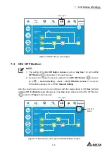
9. (1) The setting of the
2Q2ႇ%XWWRQ$FFHVV
is set as '
Any User
' for all the
ON/ OFF
Button
(
) presented in this user manual.
(2) If you want to change the access setting for the
ON/ OFF Button
(
), please
go to
SETUP
ĺ
General Setting
ĺ
User
ĺ
On/ Off Button Access
. For relevant
information, please refer to
7.10.7 General Setting
.
7.2 How to Turn on the LCD
To turn on the LCD, please follow the steps below:
1
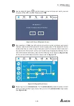
Perform one of the options (a.~ d.) below; after that, the LCD will be on and the LCD
initial screen (see
Figure 7-3
) will appear.
a. Turn on the Input Breaker (Q1); or
b. Turn on the Bypass Breaker (Q2); or
c. Turn on the Input Breaker (Q1) and Bypass Breaker (Q2); or
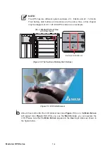
d. Turn on the external battery cabinet’s breaker (Q5), open the front door of the
UPS, and press any of the battery start buttons (
Figure 7-2
) for 1 second and
release it.
Summary of Contents for Modulon DPH series
Page 26: ......
Page 58: ......
Page 168: ......
Page 237: ...8 1 8 Optional Accessories 8 Optional Accessories...
Page 240: ......
Page 241: ...9 1 9 Maintenance Maintenance 9...
Page 243: ...A1 1 Appendix 1 7HFKQLFDO 6SHFL FDWLRQV Technical 6SHFL FDWLRQV A1 A1...
Page 246: ......
Page 247: ...A2 1 Appendix 2 Warranty Warranty A2 A2...
Page 250: ......

