5 - 1 6
Modulon DPH Series
No.
Item
Description
Function
4
Battery Input
Terminals
I/ -/ N terminals.
Connect to the external battery
cabinet(s).
5
Includes one grounding
terminal.
For the UPS’s protective earthing.
6
Includes two grounding
terminals.
For the external battery cabinet(s)
and critical loads’ grounding.
5
Make sure the Input Breaker (Q1), Bypass Breaker (Q2), Manual Bypass Breaker (Q3)
and Output Breaker (Q4) are in the
OFF
position. See
Figure 2-5
for the breakers’
location.
6
Make sure that each external battery cabinet’s breaker (Q5) is in the
OFF
position.
7
Follow
Table 5-2
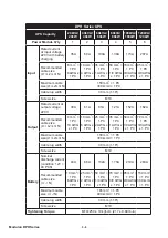
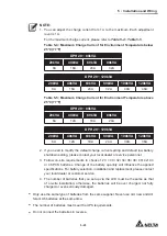
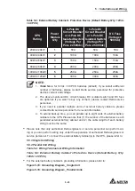
to select proper input, output, and battery cables.
8
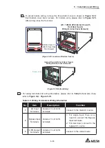
Connect the cables of the main AC source, output and external battery cabinet(s) to
the UPS. There are two types of wiring, top wiring and bottom wiring. Please refer to
the following to perform wiring.
Table 5-3: Wiring Terminals & Wiring Information
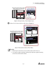
Figure 5-8: Wiring Terminals_ AC Input & Bypass Input
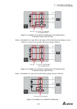
Figure 5-9: Wiring Terminals_ Battery Input
Figure 5-10: Wiring Terminals_ UPS Output
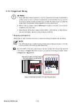
Figure 5-11: Wiring Terminals_ Grounding
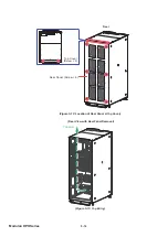
Figure 5-12: Location of Rear Panel & Top Cover
Figure 5-13: Top Entry
Figure 5-14: Location of Bottom Covers
Figure 5-15: Bottom Entry
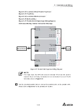
5.6 External Battery Cabinet Connection Warnings
NOTE:
For single input, the UPS will not work normally if the main AC power’s neutral
1LVQRW¿UPO\FRQQHFWHGRUQRWFRQQHFWHGWRRQHRIWKH1WHUPLQDOVVKRZQ
in
Figure 5-8
.
9
Follow
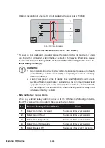
Figure 5-16
to ground the UPS, external battery cabinet(s) and connected
critical loads.
Summary of Contents for Modulon DPH series
Page 26: ......
Page 58: ......
Page 168: ......
Page 237: ...8 1 8 Optional Accessories 8 Optional Accessories...
Page 240: ......
Page 241: ...9 1 9 Maintenance Maintenance 9...
Page 243: ...A1 1 Appendix 1 7HFKQLFDO 6SHFL FDWLRQV Technical 6SHFL FDWLRQV A1 A1...
Page 246: ......
Page 247: ...A2 1 Appendix 2 Warranty Warranty A2 A2...
Page 250: ......


