41
Chapter 6 Installation and Wiring
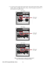
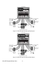
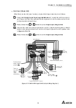
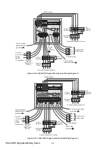
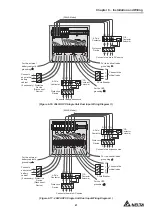
(Figure 6-16: 30kVA UPS Single Unit Dual Input Wiring Diagram II )
240V DC
240V DC
+
N
-
R
AC INPUT
S
T
N
UPS
OUTPUT
R
S
T
N
BATTERY INPUT
BYPASS BREAKER
INPUT BREAKER
R
S
T
N
R
S
T
N
I
O
ON
OFF
I
O
ON
OFF
I
O
ON
OFF
I
O
ON
OFF
I
O
ON
OFF
I
O
ON
OFF
I
O
ON
OFF
I
O
ON
OFF
(30kVA Model)
Connects the main AC source
Protective
Device
4-Pole
Contactor
R S T N
R S T N
R S T N
CS
(*CS:
Contactor
Solenoid)
For the critical loads’
grounding
For the external
battery cabinet’s
grounding
Connects the
critical loads
N
T
S
R
For the UPS
grounding
R S T N
Connects the bypass source
Protective
Device
4-Pole
Contactor
R S T N
R S T N
CS
(*CS:
Contactor
Solenoid)
3-Pole Breaker
+
N
-
Protective
Device
(Disconnect
Device)
Connects
an external
battery
cabinet
(if necessary)
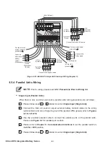
(Figure 6-17: 40kVA UPS Single Unit Dual Input Wiring Diagram I )
I
O
ON
OFF
I
O
ON
OFF
I
O
ON
OFF
I
O
ON
OFF
I
O
ON
OFF
I
O
ON
OFF
I
O
ON
OFF
I
O
ON
OFF
240V DC
240V DC
+
N
-
R
AC INPUT
S
T
N
UPS
OUTPUT
R
S
T
N
INPUT BREAKER
R
S
T
N
BYPASS BREAKER
R S
T
N
BATTERY INPUT
(40kVA Model)
Connects the bypass source
Protective
Device
4-Pole
Contactor
R S T N
R S T N
R S T N
CS
(*CS:
Contactor
Solenoid)
For the critical loads’
grounding
For the external
battery cabinet’s
grounding
Connects the
critical loads
N
T
S
R
For the UPS
grounding
R S T N
Connects the main AC source
Protective
Device
4-Pole
Contactor
R S T N
R S T N
CS
(*CS:
Contactor
Solenoid)
3-Pole Breaker
+
N
-
Protective
Device
(Disconnect
Device)
Connects
an external
battery
cabinet
(if necessary)
Summary of Contents for Ultron GES203HH33A035
Page 70: ...5013206100...

