background image


Ultron HPH Series                                                         

 61 


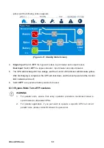
(Figure 6-18: Main Screen) 


5. 

Please log in as an 

Administrator

. For the 

Administrator 

password, please contact Delta 

service personnel. After login, ensure that you are in the 

Administrator 

login status.


6. 

Click 

SETUP 


Mode Setting 


Frequency Conversion

.


(Figure 6-19: Select Frequency Conversion Mode) 


7. 

After manually selecting 

Frequency Conversion 

mode via the touch panel, the UPS will run 

in standby mode and the output will be terminated.


8. 

Press the icon (     ) located in the upper left corner of the screen to go back to the 

Main 

Screen

.


Summary of Contents for Ultron HPH Series

Page 1: ...Delta UPS Ultron Family The power behind competitiveness www deltapowersolutions com HPH Series Three Phase 20 30 40 kVA User Manual ...

Page 2: ...l continuously improve and develop the product changes may be made to the information in this Manual at any time without obligation to notify any person of such revision or changes Delta will make all possible efforts to secure the accuracy and the integrity of this Manual Delta disclaims any kinds or forms of warranty guarantee or undertaking either expressly or implicitly including but not limit...

Page 3: ... 11 2 5 Front Panel 11 2 6 Rear Panel 13 Chapter 3 Operation Modes 17 Chapter 4 Communication Interfaces 21 4 1 Mini Slot 21 4 2 USB Port 21 4 3 RS 232 Port 21 4 4 Parallel Ports 22 4 5 External Battery Temperature Ports 22 4 6 Input Dry Contacts 23 4 7 REPO and Output Dry Contacts 25 4 7 1 REPO 25 4 7 2 Output Dry Contacts 26 Chapter 5 Installation and Wiring 28 5 1 Precautions Prior to Installat...

Page 4: ...cedures 57 6 2 6 Frequency Conversion Mode Start up Procedures 60 6 2 7 Energy Recycle Mode Start up Procedures 63 6 3 Turn off Procedures 65 6 3 1 Online Mode Turn off Procedures 65 6 3 2 Battery Mode Turn off Procedures 67 6 3 3 Bypass Mode Turn off Procedures 69 6 3 4 Manual Bypass Mode Turn off Procedures 70 6 3 5 ECO Mode Turn off Procedures 71 6 3 6 Frequency Conversion Mode Turn off Procedu...

Page 5: ...ting 103 7 9 5 Parallel Setting 108 7 9 6 Dry Contact Setting 109 7 9 7 General Setting 111 7 9 8 Control 116 7 10 Maintenance 118 7 10 1 Warning 118 7 10 2 Historical Event 119 7 10 3 Statistics 120 7 10 4 Test 121 7 10 5 Clear 121 7 10 6 Advanced Diagnosis 122 7 10 7 Version S N 123 Chapter 8 Optional Accessories 124 Chapter 9 Maintenance 125 Appendix 1 Technical Specifications 127 Appendix 2 Wa...

Page 6: ...2 Connection Warnings The UPS must be well grounded due to a possible risk of current leakage It is necessary to install protective devices when the UPS is connected to the mains and bypass source For relevant information please refer to 5 5 1 Precautions Prior to Wiring The protective devices connecting to the UPS must be installed near the UPS and must be easily accessible for operation 1 3 Usag...

Page 7: ...arameter setting of the number of batteries must be consistent with the actual number of batteries installed otherwise the battery will be overcharged or under charged and the battery may be damaged Do not dispose of the battery or batteries in a fire The batteries may explode All maintenance services must be performed by qualified service personnel Forbid opening or removing the cover of the UPS ...

Page 8: ...rged fully approximately every three months if the UPS needs to be stored for an extended period of time The charging time must not be less than 24 hours each time 1 5 Standard Compliance IEC62040 1 IEC62040 2 C2 IEC61000 4 2 ESD Level 4 IEC61000 4 3 Radiated Field Level 3 IEC61000 4 4 EFT Level 4 IEC61000 4 5 Surge Level 4 ...

Page 9: ...e With its outstanding features the UPS not only provides safe reliable and uninterrupted power to your sensitive electronic equipment at all times but also produces greater electric power efficiency at less cost 2 2 Package Inspection External During UPS transportation some unpredictable situations might occur It is recommended that you inspect the UPS exterior packaging If you notice any damage ...

Page 10: ...ler from whom you purchased the unit 3 If the UPS needs to be returned carefully repack the UPS and all of the accessories using the original packing material that came with the unit 2 3 Functions and Features The HPH series UPS is designed for systems with medium power It provides clean power supply to data systems communication systems computer network systems medical treatment systems monitorin...

Page 11: ...supplied remote control switch to disconnect the output immediately to prevent any danger Built in RS232 port allows monitoring and management of the UPS via the UPSentry 2012 software https datacenter softwarecenter deltaww com cn Attaches optional accessories like Mini SNMP card for network communication Other optional accessories include Mini Relay I O and Mini ModBus cards for dry contact and ...

Page 12: ...Ultron HPH Series 11 2 4 Appearance and Dimensions Figure 2 1 20 30 40kVA UPS Appearance and Dimensions 2 5 Front Panel Figure 2 2 Front Panel 5 Touch Panel Tri color LED Indicator ...

Page 13: ...ry appears at the top edge of the screen 3 The UPS is running in standby mode and the text Standby appears at the top edge of the screen 4 The UPS is in the soft start status and the text Softstart appears at the top edge of the screen 5 The UPS is in the energy recycle status and the text Energy Recycle appears at the top edge of the screen 6 There is a minor or medium warning and the buzzer soun...

Page 14: ...Ultron HPH Series 13 2 6 Rear Panel Figure 2 3 20kVA UPS Rear Panel ...

Page 15: ... is connected well with the UPS the user can turn on the battery switch so that the UPS can work in battery mode 2 USB Port Connects to a computer For detailed information please refer to Chapter 4 Communication Interfaces 3 RS 232 Port Connects to a computer For detailed information please refer to Chapter 4 Communication Interfaces ...

Page 16: ...formation please refer to Chapter 4 Communication Interfaces 8 MINI Slot Connects Mini SNMP Mini Relay I O Mini Mod Bus card For detailed information please refer to Chapter 4 Communication Interfaces 9 Output Breaker Connects or disconnects the UPS s loads and for safety protection 10 Input Breaker Connects or disconnects the UPS s main input power and for safety protection 11 Bypass Input Breake...

Page 17: ...cal load grounding For bypass grounding 18 Casters The casters are designed for a short distance movement only Do not use the casters to move the UPS over a long distance The casters are not designed to provide long term support for the UPS after installation please use the balance supports to support the UPS ...

Page 18: ...equipment During on line mode the LED indicator illuminates green Figure 3 1 Path of Electrical Power through the UPS in Online Mode Standby Mode When the input voltage and frequency of the main AC power are within the normal range the UPS runs in standby mode and charges the batteries The bypass and the inverter have no output The LED indicator illuminates yellow Figure 3 2 Path of Electrical Pow...

Page 19: ... the load is supplied by the inverter and the LED indicator illuminates yellow Figure 3 3 Path of Electrical Power through the UPS in ECO Mode Battery Mode When the input voltage or frequency of the UPS is out of working range the batteries provide DC power which maintains inverter operation to support the critical load During battery mode the LED indicator illuminates yellow Figure 3 4 Path of El...

Page 20: ... red flashing Bypass Mode The critical load is directly supplied by the main AC power and the batteries are charged During bypass mode the LED indicator illuminates yellow Figure 3 5 Path of Electrical Power through the UPS in Bypass Mode Frequency Conversion Mode When the UPS is manually set in frequency conversion mode the output frequency can be set as 50Hz or 60Hz After the output frequency is...

Page 21: ...PS is manually set in energy recycle mode the charger will turn off and the output power will be recycled to input Energy recycle mode is applicable to UPS self loading test only During energy recycle mode the LED indicator illuminates green Figure 3 7 Path of Electrical Power through the UPS in Energy Recycle Mode ...

Page 22: ...e provided mini card flat cable to connect the Mini slot and the UPS s CNY9 or CNY11 connector when you use the Mini SNMP Mini Relay I O or Mini Modbus card For installation information please contact Delta service personnel 4 2 USB Port USB port is located on the rear panel of the UPS Please use the provided USB cable to connect the UPS with a computer and install the UPSentry 2012 software 1 to ...

Page 23: ...aisy Chain method see Figure 5 10 Figure 5 11 to execute parallel configuration 4 5 External Battery Temperature Ports A The external battery temperature ports are used for detecting the connected external battery cabinet s temperature You need to purchase the optional external battery cabinet temperature detection cable to do that Please NOTE that this function is realized by Port 1 and Port 2 is...

Page 24: ...Positive When li ion battery BMS sent a signal NC NO adjustable to UPS UPS would stop charging to battery positive When user only have single output dry contact event user could parallel the dry contacts of Charge off positive Charge negative 6 Charge Off Negative When li ion battery BMS sent a signal NC NO adjustable to UPS UPS would stop charging to battery negative 7 External Manual Bypass Dete...

Page 25: ... Figure 4 4 shows the 1st type of configuration It requires internal power 12VSF Figure 4 4 Input Dry Contact Configuration I Figure 4 5 shows the 2nd type of configuration It requires external power with a voltage range between 6 12Vdc Figure 4 5 Input Dry Contact Configuration II 2 1 4 3 ...

Page 26: ...gency occurs Connect the REPO dry contacts to a user supplied switch and you can remotely stop the UPS output power The configuration is shown as follows Figure 4 7 REPO Port Configuration NOTE If you need more information about REPO setting please contact your dealer or Delta service personnel Only qualified Delta engineer or service personnel can modify the REPO setting 4 1 2 3 4 1 2 3 REPO Outp...

Page 27: ...age is lower than setup limit 220Vdc default 6 Bypass Input Abnormal The bypass voltage frequency or phase sequence is abnormal 7 Battery Test Fail In the process of battery test battery voltage is out of setup limit 8 Parallel Communication Fail In parallel mode parallel communication is abnormal 9 Output Overload When the UPS is overloaded or UPS shutdown the UPS transfers and runs in bypass mod...

Page 28: ... occurs the UPS will send a signal to the connected external shunt trip device to cut off the battery power 18 Backfeed Protection When the UPS s bypass SCR has an open short issue the UPS will send a signal to the connected external shunt trip device to cut off the backfeed voltage Table 4 2 Output Dry Contact Events and Description Figure 4 8 Output Dry Contacts Port Definition and Design ...

Page 29: ...orklifts Make sure that transportation routes e g corridor door gate elevator etc and installation area can accommodate and bear the weight of the UPS external battery cabinets other equipment that will be installed nearby and forklifts For the weight of the UPS please refer to Appendix 1 Technical Specifications The installation place must be kept clean and tidy at all times Ensure that the insta...

Page 30: ...S which could damage the unit If you need to move the UPS over a long distance please use appropriate equipment like a forklift Do not use the UPS casters to move the unit over a long distance 5 4 UPS Installation There are two installation methods One is with the balance supports and the other is without the balance supports Installation without the Balance Supports After moving the UPS to its fi...

Page 31: ...s If you want to install the UPS with the balance supports that have been removed from the UPS during the unpacking process please follow the following steps 1 After you decide the installation area follow the mounting hole diagram below to drill holes on the installation ground Figure 5 2 Mounting Hole Diagram ...

Page 32: ...have drilled holes use the caters to stabilize the UPS on the ground and use the M6 screws to reinstall the balance supports that have been removed from the UPS during the unpacking process on the UPS Please refer to the figure below Figure 5 3 Balance Support Installation ...

Page 33: ...e performed by qualified professional personnel If you want to install the UPS by yourself installation must be under the supervision of Delta service personnel Before wiring or making any electrical connection make sure the power supplied to the input and output of the UPS is completely cut off When connecting the UPS to the main AC power you must install a protective device that meet safety cert...

Page 34: ...Supplier 20 30 40kVA C Curve 63A Breaker Output CHNT CB 60 C63 Check that the size phase and polarity of each cable that needs connecting to the UPS is correct For the specifications of input output cables and terminal block please refer to Table 5 1 Capacity kVA 20kVA 30kVA 40kVA AC Input cable 6AWG 10mm 6AWG 10mm 4AWG 16mm Output cable 8AWG 6mm 6AWG 10mm 4AWG 16mm Battery Input cable 6AWG 10mm 4...

Page 35: ...do not share a common neutral line system add an isolation transformer to the bypass source The input of the UPS must be a Y connection and the neutral line mN bN must be connected to avoid UPS failure Do not connect the neutral line mN bN of the UPS with the ground terminal If there is a floating voltage between the input power s neutral mN bN and the ground and you require that the VNG of the UP...

Page 36: ...t please follow the following steps 1 Remove the panels shown in the figure below Figure 5 5 Panel Location 2 After removing the panels please follow the below method to modify the UPS from single input into dual input Remove the copper bars that connect the main input terminal block and bypass terminal block mL1 bL1 mL2 bL2 mL3 bL3 please see Figure 5 6 When wiring connect the main AC source s L1...

Page 37: ...unit wiring procedures are as follows 1 Remove the cover shown in Figure 5 5 and you will see the wiring terminal block shown below Figure 5 7 Wiring Terminal Block No Item Function Description Main Input Terminal Block Connects the main AC source Includes three phase mL1 mL2 mL3 and neutral mN terminals Bypass Terminal Block Connects the Bypass source Includes three phase bL1 bL2 bL3 and neutral ...

Page 38: ...ounding terminal 2 The UPS rating voltage is 220 380Vac 230 400Vac or 240 415Vac 3 The battery rating voltage is 240Vdc 4 Confirm the input breaker and bypass breaker are in the OFF position 5 According to the capacity and the model of your UPS select proper input and output cables please refer to Table 5 1 6 Connect the main AC source output external battery cabinet cables to the wiring terminal ...

Page 39: ...single input dual input setup 2 Please follow steps 1 6 stated in section Single Input Single Unit 3 Connect the main AC source bypass source output external battery cabinet cables to the wiring terminal block please refer to Figure 5 9 NOTE Regarding Figure 5 9 each figure represents that the main AC power is the TN system and a 3 pole protective device is installed between the UPS and the main A...

Page 40: ...Connect the main AC source output external battery cabinet cables to the wiring terminal block please refer to Figures 5 8 5 10 NOTE Regarding Figure 5 8 each figure represents that the main AC power is the TN system and a 3 pole protective device is installed between the UPS and the main AC power If your main AC power is the TT system please install a 4 pole protective device between the UPS and ...

Page 41: ...t between ID numbers a warning information will appear on touch panel correspondingly Figure 5 10 Parallel Units Single Input Wiring Diagram Dual Input Parallel Units When there are two AC power sources parallel units wiring procedures are as follows 1 Follow Chapter 5 5 2 Single Input Dual Input Modification to modify the UPS into dual input Please note that only authorized Delta engineers or ser...

Page 42: ...cation 5 Ground the parallel UPSs WARNING 1 When UPSs are paralleled the length of each unit s bypass input cables output cables must be equal This ensures that the parallel UPSs can equally share the equipment loads in bypass mode 2 Only UPSs with the same capacity voltage and frequency can be paralleled otherwise parallel functions will fail 3 Before start up of parallel units qualified service ...

Page 43: ...cs NOTE 1 When the number of batteries on one string is 30 34 the UPS must be derated For details please contact Delta service personnel 2 You can follow actual need to adjust the charge current from the minimum to the maximum Each adjustment level is 1A 3 If you need to modify the charge current default setting and low battery shutdown default setting please contact your local dealer or Delta ser...

Page 44: ... and 21st batteries You should use three cables to connect the external battery cabinet with the BATT BATT and BATT N terminals marked on the UPS Please refer to the below figure Figure 5 12 External Battery Cabinet Connection Please follow your UPS s rating to install an appropriate protective device for the external battery cabinet You can choose to install either an isolated switch connected in...

Page 45: ...le 5 2 When choosing the external battery cabinet s protective device please take the following factors into consideration 1 overcurrent between the UPS and battery circuit 2 fault current 3 wire cable material and 4 local electrical regulations If you have any questions about the external battery cabinet s protective device please contact Delta service personnel Please refer to Figure 5 13 5 15 f...

Page 46: ...es WARNING 1 Each block of battery needs to be insulated with metal of cabinet Earth when battery assembly 2 A battery can present a risk of electric shock and high short circuit current Servicing of batteries and battery cabinets must be performed or supervised by qualified service personnel knowledgeable in batteries battery cabinets and the required precautions Keep unauthorized personnel away ...

Page 47: ... will sound an alarm Please see the table below No External Battery Cabinet Status Alarm 1 Battery Test Fail Sounds once every 0 5 seconds 2 Battery End of Discharge Imminent Sounds once every 0 5 second 3 Battery End of Discharge Long beep 5 seconds 4 Battery Over Charge Long beep 5 Battery Missing Sounds once every 0 5 seconds ...

Page 48: ...Units 1 You can parallel at maximum four UPS units 2 For parallel units ensure that each parallel cable provided is connected well 3 Make sure that all of breakers including every external battery cabinet s breaker are turned to the OFF position 4 Check if the wiring is correct Ensure that the input power s voltage frequency phase and NOTE 1 All the information on the touch panel presented in this...

Page 49: ...rn off procedures 6 2 Start up Procedures 6 2 1 Online Mode Start up Procedures WARNING 1 For parallel units please follow Chapter 6 2 3 Bypass Mode Start up Procedures to turn on each parallel UPS After confirming that parallel operation can be normally run follow the following procedures step by step 2 For parallel units ensure that every operation procedure mentioned below is synchronized to al...

Page 50: ... Main Screen 5 Press the ON OFF button once and the following screen will pop up to ask you if you want to power on the UPS s inverter If yes please select Power On Please refer to the below figure Figure 6 2 Power On Reminder Screen ...

Page 51: ...After confirming that parallel operation can be normally run follow the following procedures step by step 2 For parallel units ensure that every operation procedure mentioned below is synchronized to all parallel UPSs 3 For parallel application if you just want to operate a specific UPS but not all parallel ones please contact Delta service personnel 1 Ensure that the manual bypass breaker is in t...

Page 52: ...ate a specific UPS but not all parallel ones please contact Delta service personnel 1 Ensure that the manual bypass breaker is in the OFF position 2 Switch ON each external battery cabinet s breaker 3 Single Input Switch ON the bypass breaker and the input breaker Dual Input Switch ON the bypass breaker and the input breaker 4 After you switch ON the bypass breaker input breaker the UPS will start...

Page 53: ... settings must be the same 6 For parallel application M S will appears behind each parallel UPS s parallel ID No and parallel group No which is located in the upper left corner of the screen The UPS with M is master unit and the one with S is slave unit e g UPS 1 2 M Please see the below figure Figure 6 6 Parallel UPS Status 7 For single unit switch ON the output breaker For parallel units switch ...

Page 54: ... manual bypass mode the connected critical loads will be supplied by the manual bypass and the output won t be protected Please ensure that the bypass AC source is normal 4 In manual bypass mode the connected critical loads will be supplied by the manual bypass thus maintenance personnel can perform maintenance without interrupting the power supplying to the critical loads 5 Ensure that all of the...

Page 55: ...e figure below At this time the tri color LED indicator will illuminate green Figure 6 8 Online Mode Screen 2 Press the ON OFF button once and the following screen will pop up to ask you if you want to power off the UPS s inverter If yes please select Power Off If not please select Cancel Figure 6 9 Power Off Reminder Screen ...

Page 56: ...tput breaker 6 The UPS will discharge DC bus voltage and the tri color LED indicator will illuminate yellow After discharging is completed the UPS will shut down and the touch panel and the tri color LED indicator will be off 7 Switch OFF each external battery cabinet s breaker Switching from manual bypass mode to online mode WARNING 1 For parallel units ensure that every operation procedure menti...

Page 57: ... range the UPS will transfer to run in bypass mode the screen will show as follows and the tri color LED indicator will illuminate yellow Figure 6 11 Manual Bypass Mode Screen 5 Switch OFF the manual bypass breaker and lock the cover of manual bypass breaker 6 Press the ON OFF button once and the following screen will pop up to ask you if you want to power on the UPS s inverter If yes please selec...

Page 58: ...lowing procedures step by step 2 For parallel units ensure that every operation procedure mentioned below is synchronized to all parallel UPSs 3 For parallel application if you just want to operate a specific UPS but not all parallel ones please contact Delta service personnel 1 Ensure that the manual bypass breaker is in the OFF position 2 Switch ON each external battery cabinet s breaker 3 Singl...

Page 59: ... to run in bypass mode the screen will show as follows and the tri color LED indicator will illuminate yellow Figure 6 14 Main Screen 5 Please log in as an Administrator For the Administrator password please contact Delta service personnel After login ensure that you are in the Administrator login status 6 Click SETUP Mode Setting ECO Figure 6 15 Select ECO Mode ...

Page 60: ...On Reminder Screen 9 After selection of Power On to start up the UPS s inverter the UPS will start up and perform self inspection At the same time the UPS begins synchronization with the bypass AC source After the self inspection is completed the UPS will automatically transfer to run in online mode After the system confirms that the bypass voltage is normal the UPS will automatically switch to ru...

Page 61: ... Ensure that the manual bypass breaker is in the OFF position 2 Switch ON each external battery cabinet s breaker 3 Single Input Switch ON the bypass breaker the input breaker and the output breaker Dual Input Switch ON the bypass breaker the input breaker and the output breaker 4 After you switch ON the bypass breaker and the input breaker the UPS will start up the main screen will appear after a...

Page 62: ...hat you are in the Administrator login status 6 Click SETUP Mode Setting Frequency Conversion Figure 6 19 Select Frequency Conversion Mode 7 After manually selecting Frequency Conversion mode via the touch panel the UPS will run in standby mode and the output will be terminated 8 Press the icon located in the upper left corner of the screen to go back to the Main Screen ...

Page 63: ...r selection of Power On to start up the UPS s inverter the UPS will start up and perform self inspection After the self inspection is completed the UPS will automati cally transfer to run in frequency conversion mode and the output frequency will be the same as setup value Now the tri color LED indicator illuminates green and the following screen appears Figure 6 21 Frequency Conversion Mode ...

Page 64: ...bypass breaker and the input breaker the UPS will start up the main screen will appear after about 25 seconds and the tri color LED indicator will illuminate yellow After the UPS finishes establishing DC BUS voltage the charger will start to charge the batteries If the bypass voltage is within the normal range the UPS will transfer to run in bypass mode the screen will show as follows and the tri ...

Page 65: ...he touch panel press the icon located in the upper left corner of the screen to go back to the Main Screen 8 Press the ON OFF button once and the following screen will pop up to ask you if you want to power on the UPS s inverter If yes please select Power On Figure 6 24 Power On Reminder Screen ...

Page 66: ...ode Now the tri color LED indicator illuminates green and the following screen appears Figure 6 25 Energy Recycle Mode 6 3 Turn off Procedures 6 3 1 Online Mode Turn off Procedures WARNING 1 For parallel units ensure that every operation procedure mentioned below is synchronized to all parallel UPSs 2 For parallel application if you just want to operate a specific UPS but not all parallel ones ple...

Page 67: ...een will pop up to ask you if you want to power off the UPS s inverter If yes please select Power Off Figure 6 27 Power Off Reminder Screen 3 After selection of Power Off the UPS will shut down the inverter and let the bypass AC source supply power If the bypass AC source is abnormal there is a risk of output interruption and the connected critical loads won t be protected At this moment the UPS ...

Page 68: ...e DC bus voltage and the tri color LED indicator will illuminate yellow After discharging is completed the UPS will shut down and the touch panel and the tri color LED indicator will be off 6 Switch OFF every external battery cabinet s breaker 6 3 2 Battery Mode Turn off Procedures WARNING 1 For parallel units ensure that every operation procedure mentioned below is synchronized to all parallel UP...

Page 69: ... ON OFF button once and the following screen will pop up to ask you if you want to power off the UPS s inverter If yes please select Power Off Figure 6 30 Power Off Reminder Screen 3 After selection of Power Off the UPS will shut down the inverter terminate the output and transfer to run in standby mode At this moment the tri color LED indicator illuminates ...

Page 70: ...r LED indicator will illuminate yellow After discharging is completed the UPS will shut down and the touch panel and the tri color LED indicator will be off 6 Switch OFF every external battery cabinet s breaker 6 3 3 Bypass Mode Turn off Procedures WARNING 1 For parallel units ensure that every operation procedure mentioned below is synchronized to all parallel UPSs 2 For parallel application if y...

Page 71: ...ll shut down and the touch panel and the tri color LED indicator will be off 4 Switch OFF every external battery cabinet s breaker 6 3 4 Manual Bypass Mode Turn off Procedures WARNING 1 For parallel units ensure that every operation procedure mentioned below is synchronized to all parallel UPSs 2 For parallel application if you just want to operate a specific UPS but not all parallel ones please c...

Page 72: ...ocedures WARNING 1 For parallel units ensure that every operation procedure mentioned below is synchronized to all parallel UPSs 2 For parallel application if you just want to operate a specific UPS but not all parallel ones please contact Delta service personnel 1 In ECO mode the touch panel shows the following screen and the tri color LED indicator illuminates green Figure 6 33 ECO Mode Screen ...

Page 73: ...der Screen 3 After selection of Power Off the UPS will shut down the inverter terminate the output and transfer to run in bypass mode If the bypass AC source is abnormal there is a risk of output interruption and the connected critical loads won t be protected At this moment the tri color LED indicator illuminates yellow and the following screen appears Figure 6 35 Bypass Mode Screen ...

Page 74: ... and output breaker 7 The UPS will discharge DC bus voltage and the tri color LED indicator will illuminate yellow After discharging is completed the UPS will shut down and the touch panel and the tri color LED indicator will be off 8 Switch OFF every external battery cabinet s breaker 6 3 6 Frequency Conversion Mode Turn off Procedures WARNING 1 For parallel units ensure that every operation proc...

Page 75: ...on once and the following screen will pop up to ask you if you want to power off the UPS s inverter If yes please select Power Off Figure 6 38 Power Off Reminder Screen WARNING Please note that once you select Power Off all power will be completely cut off Please make sure that the critical loads connected to the UPS have already been safely shut down before you perform the turn off procedures ...

Page 76: ...r LED indicator illuminates yellow and the following screen appears Figure 6 39 Standby Mode Screen 4 Switch OFF output breaker and log in as an Administrator For the Administrator password please contact Delta service personnel After login ensure that you are in the Administrator login status 5 Click SETUP Mode Setting On Line If the bypass voltage is in the normal range the UPS will run in bypas...

Page 77: ...the touch panel and the tri color LED indicator will be off 8 Switch OFF every external battery cabinet s breaker 6 3 7 Energy Recycle Mode Turn off Procedures WARNING 1 Energy mode is just for UPS aging test and is only applicable for single unit single input The output does not need to take any load 2 In energy recycle mode the charger is turned off 1 In energy recycle mode the touch panel shows...

Page 78: ...PS will stop aging test and run in bypass mode At this moment the tri color LED indicator illuminates yellow and the following screen appears Figure 6 43 Bypass Mode Screen 4 Switch OFF output breaker and log in as an Administrator For the Administrator password please contact Delta service personnel After login ensure that you are in the Administrator login status 5 Click SETUP Mode Setting On Li...

Page 79: ...ch OFF the bypass breaker input breaker and output breaker 7 The UPS will discharge DC bus voltage and the tri color LED indicator will illuminate yellow After discharging is completed the UPS will shut down and the touch panel and the tri color LED indicator will be off 8 Switch OFF every external battery cabinet s breaker ...

Page 80: ...Ultron HPH Series 79 Chapter 7 Touch Panel Display and Settings 7 1 Touch Panel Display Hierarchy ...

Page 81: ...80 ...

Page 82: ...he ADMINISTRATOR password is needed For password information please refer to 7 5 Password Entry 2 The items marked with 1 need to be carried out by qualified service personnel please contact Delta service personnel for assistance 3 2 reserved for inbuilt battery model ...

Page 83: ... touch panel will then light up or c Switch ON the external battery cabinet s breaker and press the battery start button on the rear panel of the UPS for 3 seconds and release it after you hear one beep the touch panel will then light up 2 About 25 seconds after the touch panel lights up the main screen will appear as follows And now the touch panel can be used Please note that when the main scree...

Page 84: ...it indicates that the UPS s inverter is in the OFF status Press the button once the following reminder window will pop up to ask you if you want to power on the UPS s inverter If yes please select Power On After selecting Power On the ON OFF button will turn green indicating that the UPS is starting up or the power on process is completed Figure 7 4 Power On Reminder Window ON OFF Button ...

Page 85: ...nd the following reminder window will pop up to ask you if you want to power off the UPS s inverter If yes please select Power Off After selecting Power Off the ON OFF button will turn gray indicating that the power off process is completed Figure 7 5 Power Off Reminder Window 7 4 Introduction of Touch Panel and Function Keys ...

Page 86: ...ith S is slave unit On Line Mode Battery Mode Bypass Mode Standby Mode Softstart Mode Fault Mode Remote Mode Energy Recycle Mode ECO Mode Frequency Conversion Mode Indicates the operation status of the UPS The actual display will depend on the actual operation status User Indicates login by User Administrator Indicates login by Administrator Indicates the date and time Yes Back to the main screen ...

Page 87: ...ng event shortcut button The numerical value at the upper right of the warning icon indicates the number of current warning events You can press the icon to check the exact warning information Yes 1 Buzzer button 2 If any warning event occurs the buzzer will sound By clicking the buzzer button the buzzer will be muted At this time the buzzer disabled symbol will appear ON OFF button For more infor...

Page 88: ...tcut button Bypass static switch status green ON gray OFF Rectifier status green normal gray waiting or OFF 1 Inverter status green normal gray waiting or OFF 2 Inverter output screen shortcut button 1 Output status green normal gray no output 2 Load capacity 3 Output screen shortcut button Other symbols which will appear during the operation of the touch panel are shown in the table below No Symb...

Page 89: ...icating Administrator login is successful 3 To change the Administrator password click General Setting Admin Password change the Administrator Password 4 digits 4 After finishing the settings click to log out and be back to the main screen in the User login status Or if idling for a moment until the back light of touch panel is off the administrator account will log out automatically And then touc...

Page 90: ...ee the examples below A The screen below indicates that the UPS is in online mode and the loads are supplied by the inverter About how to set up online mode please refer to 7 9 2 Mode Setting and 6 2 1 Online Mode Start up Procedures B The screen below indicates that the UPS is in standby mode The inverter is not turned on and the bypass is out of range ...

Page 91: ...e The inverter is in the ready to power on status and the loads are supplied by the bypass power About how to set up ECO mode please refer to 7 9 2 Mode Setting and 6 2 5 ECO Mode Start up Procedures D The screen below indicates that the UPS is in battery mode ...

Page 92: ... and the inverter is not turned on F The screen below indicates that the UPS is in frequency conversion mode and the bypass output is restricted About how to set up frequency conversion mode please refer to 7 9 2 Mode Setting and 6 2 6 Frequency Conversion Mode Start up Procedures ...

Page 93: ...eck the Power Flow and Summary respectively Please see the figure below Press the Power Flow button to check the UPS s power flow diagram shown in the figure below Press the Summary button to check information related to input output and battery shown in the figure below ...

Page 94: ...Ultron HPH Series 93 1 Input information includes Main Voltage and Bypass Voltage 2 Output information includes Frequency Total Output Power Voltage Current Power and Load ...

Page 95: ... Remaining Capacity Remaining Time Voltage and Current 7 8 Measurement There are five shortcut buttons for you to check the Main Input Bypass Input Inverter Output UPS Output and Battery Status respectively Please see the figure below ...

Page 96: ... screen you can inquire about the Phase Voltage Line Voltage Current Frequency DC BUS Voltage and Kilowatt Hour readings 7 8 2 Bypass Input In the Bypass Input screen you can inquire about the Phase Voltage Line Voltage Frequency and Kilowatt Hour readings ...

Page 97: ... you can inquire about the Phase Voltage Line Voltage Current and Frequency readings 7 8 4 UPS Output In the UPS Output screen you can inquire about the Phase Voltage Line Voltage Current Load Apparent Power Active Power Power Factor and Frequency readings ...

Page 98: ... 5 Battery Status In the Battery Status screen you can inquire about the Status Voltage Current Remaining Capacity Remaining Time Estimated Recharging Time Test Result Battery Temp Charger Voltage and Charger Current readings ...

Page 99: ...ntrol respectively Please see the figure below 7 9 1 Bypass Setting In the Bypass Setting screen the administrator can set up the Bypass Frequency Range Bypass Voltage Max Bypass Voltage Min ECO Voltage Max and ECO Voltage Min If the range is exceeded the system will issue an alarm These settings must be performed by qualified service personnel please contact Delta service personnel for assistance...

Page 100: ...t s frequency range Bypass Voltage Max Set up the bypass output s maximum voltage Bypass Voltage Min Set up the bypass output s minimum voltage ECO Voltage Max Set up the bypass output s maximum voltage in ECO mode ECO Voltage Min Set up the bypass output s minimum voltage in ECO mode ...

Page 101: ...PS in ECO mode In ECO mode it is the bypass to supply power to the connected loads It is suggested that you set the UPS in ECO mode only when there is stable main AC power Otherwise power supply quality will be compromised Energy Recycle Set up the UPS in energy recycle mode In energy recycle mode the output with load can be simulated for the aging test without real output to the loads Frequency C...

Page 102: ...the administrator can set up Voltage Frequency Slew Rate System Redundancy Asnyc Transfer Time Industrial Mode Bypass Disable and System Sequential Start These settings must be carried out by qualified service personnel please contact Delta service personnel for assistance ...

Page 103: ... The system will automatically select the output frequency in accordance with the bypass power NOTE The frequency can be modified only when the inverter is powered off that is bypass mode or standby mode Slew Rate Set up the maximum permissible speed for the UPS output frequency to catch up the bypass frequency variation NOTE The slew rate can be modified only when the inverter is powered off that...

Page 104: ...etup time Industrial Mode Set up the industrial mode disable or enable default Bypass Disable Set up the bypass disable disable default or enable System Sequential Start Set up the time interval for the UPS to be converted from the battery mode to online mode The setup is applicable to the generator to avoid bearing the whole loads right away 7 9 4 Battery and Charging Setting In the Battery and C...

Page 105: ...104 ...

Page 106: ...Ultron HPH Series 105 ...

Page 107: ... the battery power will cut off the UPS will shut down and the connected loads won t be protected Battery Test Fail Voltage 1 Set up the battery test fail voltage Float Charge Voltage 1 Set up the float charge voltage Equalized Charge Voltage Set up the equalized charge voltage Charge Current Max 1 Set up the maximum charge current Auto Equalized Charge Enable or disable the auto equalized charge ...

Page 108: ... li ion batteries 1 Please set up the items marked with 1 in the above table according to the li ion batteries characteristics of different li ion manufacturers If the li ion battery BMS Battery Management System needs to control the charging switch of li ion batteries please connect the output control signal to the input dry contacts of the UPS and set up the status of the input dry contacts Char...

Page 109: ... connection and let the loads be evenly distributed among the parallel units If the parallel UPSs have different parallel group ID No their output signals might be synchronized but their outputs cannot be connected in parallel Parallel ID The UPSs that need to be paralleled must be assigned the same parallel group ID No and different parallel ID No in order to let the parallel function work Common...

Page 110: ...ry Contact Setting In the Dry Contact Setting screen you can set up the events of input and output dry contacts These settings must be carried out by qualified service personnel please contact Delta service personnel for assistance ...

Page 111: ...act Events and Descrip tion Set up NO normally open or NC normally closed for each input dry contact Output 1 Output 2 Output 3 Output 4 Select one of the following events as the setting for each output dry contact For detail setting please refer to Table 4 2 Input Dry Contact Events and Descrip tion Set up NO normally open or NC normally closed for each output dry contact ...

Page 112: ...g In the General Setting screen the user can set up Date Format Date Time Screen Brightness Screen Sleep after and Language Other settings must be carried out by qualified service personnel please contact Delta service personnel for assistance ...

Page 113: ...112 ...

Page 114: ...Ultron HPH Series 113 ...

Page 115: ...eep time default 1 minute User Language Set up the display language default English Admin Password Set up the administrator password 4 digits Dust Filter Dust Filter Installation If you have installed the dust filter please select Enable The default setting is Disable Dust Filter Installation Date Set up the dust filter installation date NOTE Only when you select Enable for Dust Filter Install ati...

Page 116: ...n Date Set up the fan installation date NOTE Only when you select Enable for Fan Replacement Warning can you set up the Fan Installation Date Estimated Fan Replacement Date Set up the fan replacement date When the date is due the alarm message Replace Fan will be displayed in touch panel NOTE Only when you select Enable for Fan Replacement Warning can you set up the Estimated Fan Replacement Date ...

Page 117: ...llation date NOTE Only when you select Enable for IGBT Replace ment Warning can you set up the IGBT Installation Date Estimated IGBT Replacement Date Set up the IGBT replacement date When the date is due the alarm message Replace IGBT will be displayed in touch panel NOTE Only when you select Enable for IGBT Replace ment Warning can you set up the Estimated IGBT Replacement Date 7 9 8 Control In t...

Page 118: ...in auto equalized charge mode to charge the batteries Force Bypass to Inverter Manually force the UPS to switch from bypass to inverter when the inverter keeps staying in the soft start status and is unable to transfer to on line mode successfully Force Inverter to Bypass Manually force the UPS to switch from inverter to bypass when any emergency occurs ...

Page 119: ...ng Historical Event Statistics Test Clear Advanced Diagnosis and Version S N respectively Please see the figure below 7 10 1 Warning When there is a warning the buzzer will make an alarm sound Click the warning icon to enter the Warning screen In the Warning screen you can inquire the warning logs and solutions The system can store at maximum 200 warning logs NOTE Click the number on the right sid...

Page 120: ...o can click the download icon to download the historical event logs The UPS can save up to 10000 historical event logs NOTE 1 The download icon will appear at the upper right corner of the screen only after inserting the U disk into the USB communication port 2 Click the number on the right side of the historical event screen as shown in the figure below and enter a specific page number you can qu...

Page 121: ...eration Time Item Description On Battery Mode Means how many times that the UPS runs in battery mode Battery Mode Duration Means how long the UPS runs in battery mode On Bypass Mode Means how many times that the UPS runs in bypass mode Bypass Mode Duration Means how long the UPS runs in bypass mode Operation Time Means how long the UPS has operated ...

Page 122: ...reen the user can perform Buzzer LED Test and the administrator can perform Manual Battery Test and Battery Depth of Discharge Test 7 10 5 Clear In the Clear screen you can clear the records of Statistics kWH Historical Event and Battery Test Result ...

Page 123: ...nt information for UPS analysis and maintenance Do not clear any of them without the consent of qualified service personnel 7 10 6 Advanced Diagnosis In the Advanced Diagnosis screen the administrator can check System Temperature and INV Temperature ...

Page 124: ... Model Name S N Touch Panel FW Version and System FW Version and can upgrade Touch Panel FW version and System FW version Touch Panel FW version and System FW version upgrading must be carried out by qualified service personnel please contact Delta service personnel for assistance ...

Page 125: ...ontacts 4 Mini ModBus Card Lets the UPS have Modbus communication function 5 EnviroProbe 1000 Monitors temperature humidity and other connected monitor ing devices in a room environment The EnviroProbe 1000 should work with Mini SNMP card or EnviroStation 6 EPO Kit For UPS emergent power off 7 IP42 Kit Prevents dust and water drops from entering into the UPS to ensure UPS reliability and to prolon...

Page 126: ...eck if any error overload internal fault etc occurs 3 Whether battery voltage is normal If the battery voltage is too high or too low find the root cause Batteries The HPH Series UPS uses sealed lead acid batteries The battery life depends on the environment temperature the usage and the charging discharging frequency High temperature environments and high charging discharging frequency will quick...

Page 127: ...f all of the fans work normally and make sure if the ventilation air can move freely around and through the UPS If not replace the fans immediately NOTE Please ask your local dealer or customer service for more maintenance information Do not perform maintenance if you are not trained for it ...

Page 128: ...8A Power Factor 0 99 full load Output Voltage 220 380 Vac 230 400 Vac 240 415 Vac Power Factor 1 Voltage Regulation 1 Voltage Harmonic Distortion 1 5 linear load Overload Capability 105 continuous 105 110 60 minutes 110 125 10 minutes 126 150 1 minute 150 1 second Output Frequency 50 60 Hz 0 05 Hz Crest Factor 3 1 Efficiency Online Mode Up to 96 ECO Mode Up to 99 Battery Charger Type SMF VRLA Batt...

Page 129: ...Port x 1 Input Dry Contact x 2 Output Dry Contact x 4 Manual Bypass Switch Yes Physical Dimensions W D H 240 x 630 x 650 mm Weight 44kg 50kg 50kg Environment Operating Altitude 1000 meters without de rating Operating Temperature 0 40 C Relative Humidity 0 95 non condensing NOTE 1 Please refer to the rating label for the safety rating 2 All specifications are subject to change without prior notice ...

Page 130: ...stible force i e war fire natural disaster etc and this warranty also expressly excludes all incidental and consequential damages Maintenance service for a fee is provided for any damage out of the warranty period If any maintenance is required please directly contact the supplier or Seller WARNING The individual user should take care to determine prior to use whether the environment and the load ...

Page 131: ...ill VIC 3168 Australia T 61 3 9543 3720 E ups australia deltaww com Delta Electronics Korea Inc 1511 Byucksan Digital Valley 6 cha Gasan dong Geumcheon gu Seoul Korea 153 704 T 82 2 515 5303 E ups south korea deltaww com Delta Electronics Int l Singapore Pte Ltd 4 Kaki Bukit Ave 1 05 04 Singapore 417939 T 65 6747 5155 E ups singapore deltaww com Australia Thailand South Korea Singapore Delta Elect...

Page 132: ...5013285200 ...

Reviews: