10
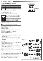
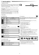
7.3 Wing Movement Direction
7.4 Basic Settings
Before programming, move the gate manually in the middle position and re-engage
release mechanism (see page 6). Press and hold the “
–
“ button on the control
board and ensure that the motor is moving in
CLOSE
direction. If correct, immedia-
tely let go of the “-“ button and gate stops.
If motor is moving in
OPEN
direction, go to the functions “
d1
“ and change the
direction settings.
Once
CLOSE
direction is set correctly, leave the gate in the middle position. The
operator is ready for the Learning phase.
Note: gate can be moved with “+“ and “-“ buttons prior to final settings if required.
Press and hold the “+“ button on the control board to move the gate into
OPEN
position. When button is released operator stops.
Press and hold the “–“ button on the control board to move the gate into
CLOSE
position. When button is released operator stops.
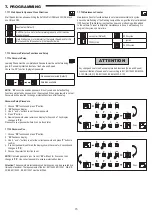
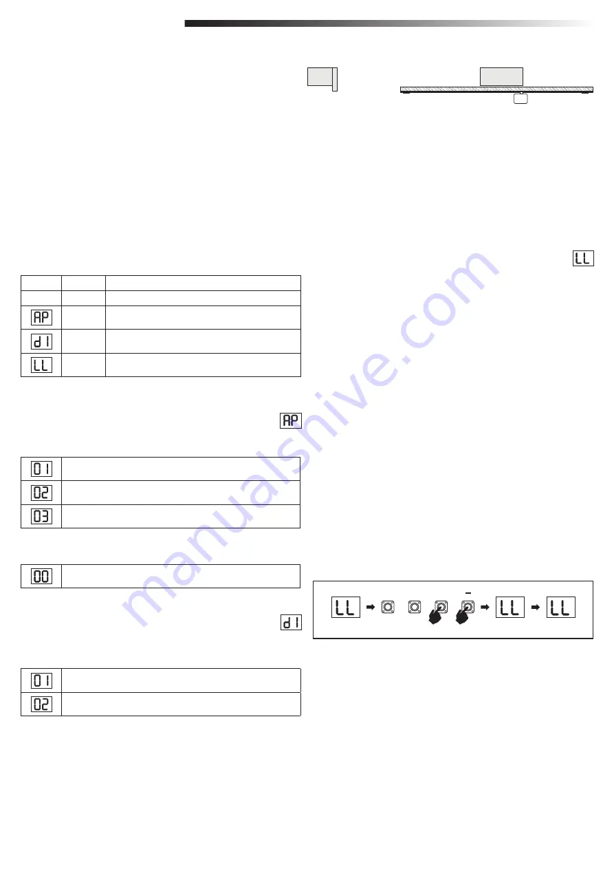
LED
Function
Basic Settings (mandatory)
AP
Application
d1
Direction Motor 1
LL
Limit Learning Phase
Basic Settings Overview
Direction Motor function shown on display
Defines movement direction of the Motor.
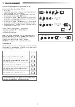
7.4.2 Direction Motor Settings
Motor is installed on
left hand side
(default).
Motor is installed on
right hand side
.
P
+
S
2 sec.
III
III
3 sec.
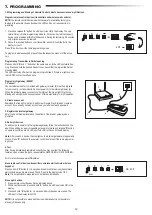
Application function shown on display.
This function is already pre-set at factory at correct value as defined for
the delivered operator.
7.4.1 Application Settings
Sliding gate, SL400
Sliding gate, SL600
Sliding gate, SL1000
More settings available on demand:
No application selected
Available Learning methods:
Before starting a Learning phase ensure that:
1. Other Basic Settings are completed
2. Magnets are installed and working correctly
3. First movement will be in
CLOSE
direction.
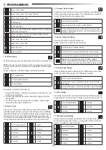
1. OPEN the LL menu.
2. Press and hold “
+
and
–“
buttons for 2 seconds.
3. Automatic learning process starts.
LL
will flash on the display during complete
-
process.
4. Gate moves in
CLOSE
direction until the
CLOSE
limit switch is reached, and-
stops for 2 seconds., then moves in the
OPEN
direction.
5. Gate moves in
OPEN
direction until the open limit switch is reached.
6. Gate moves in
CLOSE
direction until the close limit switch is reached, and-
stops.
7.
Standard Learning phase is finished.
LL
will appear on display and board will
return in stand-by mode after 3 seconds.
Standard Learning Mode (Automatic)
Values 04, 05, 06 and 07 are not suitable for SL application and shall not be chosen
Assure that the Limit positions are checked and the door is in the the middle
position to start the Limit Learning Learning Phase.
Before Limit Learning Phase can be started the preparation for the learning
of the end limit position must be done as described in the section Limit
switch position Set up.
7.4.3 Limit Learning
Following settings are done during Standard Learning Mode:
1. Travel length from
FULL CLOSED
to
FULL OPEN
position.
2. Opening and closing force.
3. 60 cm of travel travel in both directions is assigned for Soft Stop.
7. PROGRAMMING


