background image

19

11. MAINTENANCE

Battery of the remote control:

The batteries in the remote have an extremely long life. If the transmission range decreases, the batteries must be replaced. Batteries are not covered by the guarantee.

Please observe the following instructions for battery:

Batteries should not be treated as household waste. All consumers are required by law to dispose of batteries properly at the designated collection points. Never recharge 

batteries that are not meant to be recharged.

Danger of explosion!

Keep batteries away from children, do not short-circuit them or take them apart. See a doctor immediately, if a battery is swallowed. If necessary, clean contacts on battery 

and devices before loading. Remove flat batteries from the device immediately!

Increased risk of leakage!

Never expose batteries to excessive heat such as sunshine, fire or similar!

There is increased risk of leakage!

Avoid contact with skin, eyes and mouth. Rinse the parts affected by battery acid with plenty of cold water and consult a doctor immediately. Use only batteries of the 

same type. Remove the batteries if the device is not being used for a long time.

Replacing battery:

To replace battery, turn remote control around and open the case with a screwdriver. Lift cover and lift control board below. Slide battery to one side and remove. Watch 

polarity of battery! Assemble again from in reverse direction.

ATTENTION!

Danger of explosion if battery is replaced improperly. Replacement only by identical or equivalent type (CR2032) 3V.

The drive mechanism is maintenance free. Check the gate fittings and the drive mechanism at regular intervals (monthly) are securely fixed. Release the drive and check 

that the gate functions properly. Unless the gate runs smoothly it will not operate correctly with the drive mechanism. The drive cannot eliminate the problems caused by a 

gate that does not work correctly.

These settings must be checked and undertaken properly during the installation of the opener! Due to weathering, minor changes can occur during operation of the ope-

ner that need to be addressed by a new setting. This can particularly happen in the first year of operation. Follow the instructions for setting travel limits and force (refer to 

section Limit Learning Phase, pages 11 and 12) carefully and re-check the automatic safety reverse after each resetting!

IMPORTANT Notice! 

Follow the safety notices. See “Safety instructions” (pages 2 and 3). The sequence described  in the “installation” section, but in opposite order. 

Ignore the setup instructions.

Your statutory rights are not affected by this manufacturer‘s warranty. Please see www.liftmaster.eu for terms of warranty.

Our electrical and electronic equipment may not be disposed of with household waste and must be disposed of after use properly in accordance with WEEE Direc

-

tive EU: 2012/19/EU; GB UK(NI): SI 2012 nr. 19 on waste electrical and electronic equipment in order to ensure that materials are recycled.  Collecting waste elect

-

rical equipment separately means environmentally-friendly disposal and is completely free of charge for the consumer. WEEE reg. no. in Germany: DE66256568. 

Any waste packaging left over with the end consumer must be collected separately from mixed waste, in accordance with the Directive. Packaging may not be disposed 

of with household waste, organic waste or in nature. Packaging material must be separated according to its material and disposed of in the recycling containers provided 

and in certain council recycling bins.

Replace Batteries in The Remote Control

The drive mechanism

Limit switch adjustment and force regulation

Disassembly

Our batteries are marketed in compliance with the law. The ‘crossed-out waste bin’ indicates that batteries may not be disposed of with household waste. Batteries 

included in the product (technical data). In order to avoid causing harm to the environment or people’s health, used batteries must be returned for regulated dis-

posal at council recycling centres or via retail outlets, as is prescribed by law. Batteries may only be brought for disposal once fully discharged and, in the case of lithium 

batteries, with their terminals taped over. The batteries can be easily removed from our equipment for disposal. Registration number in Germany: 21002670.

The manual consists of these operating instructions and the declaration of conformity.

The radio equipment type (TX4EVF) is in compliance with Directive 2014/53/EU and for UK with Radio Equipment Regulation SI 2017 No. 1209. 


The full text of the EU declaration of conformity is available at the following internet address: https://doc.chamberlain.de

CAUTION

Risk of explosion if the battery is replaced by an incorrect type.

Do not ingest battery, Chemical Burn Hazard.

This product contains a coin battery. If swallowed, button batteries can cause injuries, or death.

WARNING

•  Keep batteries out of sight and out of the reach of children, button/coin batteries can be dangerous for children.

•  Dispose of used button batteries immediately. Do not use defect/swallowed batteries.

•  Check periodically if the battery compartments is secure, stop using if defect.

•  If batteries might have been swallowed or placed inside any part of the body, seek immediate medical attention.

12. DISPOSAL

13. WARRANTY

14. DECLARATION OF CONFORMITY

Summary of Contents for LiftMaster SL1000EVK

Page 1: ...Operator Installation Manual fr Manuel d installation de l op rateur de portail coulissant nl Installatiehandleiding schuifhekaandrijving For GB UK NI specific information on national regulations and...

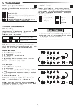
Page 2: ...Learning 10 7 5 Stand by Mode 11 7 6 Programming and Erasing of Remote Controls Radio Accessories and myQ Devices 12 7 7 Advanced Settings 13 7 7 1 Overview Advanced Settings 13 7 7 2 Transmitter Set...

Page 3: ...tions to avoid personal injury or damage to property Read these instructions carefully Warnings Symbols The general warning symbol indicates a danger that can lead to injuries or death In the text sec...

Page 4: ...le locations The gate opener should ONLY be used if the user can see the entire gate area and is assured that it is free of obstacles and the gate operator is set correctly No one may pass through the...

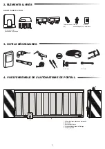
Page 5: ...control board Release Key 2x Remote Control 2x Installation Manual 1 2 3 3 4 5 4 1 Motor with control board 2 Rack 3 Magnet brackets 4 Infrared photocells 5 Flashing lamp 8 13 mm 8 13 mm 2 DELIVERY SC...

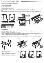
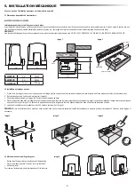
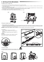
Page 6: ...Add a washer and insert it from the bottom into base plate Secure from top with a second nut 2 Repeat for remaining 3 anchor screws see picture 3 3 Get the prepared cables see picture 4 through the ho...

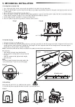
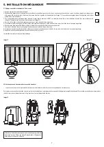
Page 7: ...el or nylon rack can be attached by welding steel only or with screws see picture 9 Put the first rack segment at the end of the gate so that it connects to the operator sprocket as shown in the pictu...

Page 8: ...se position on the opposite side of the gate 7 When reached section of the lower right digital on display will be on 8 If needed adjust the position of the magnet verify that the lower right digital w...

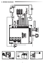
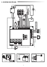
Page 9: ...OR 2 WHT GRN RED WHT GRN RED MOTOR 1 M CN4 BAT BAT 24V BATTERY POW 24V SPEC 24VDC SYNC STBY UART LIMIT SW E LK FLA COMMAND IR SENSOR EDGE 24V BAT 8 2K SAFETY EDGE NC NO NO Stop Fully Open Partial Open...

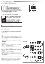
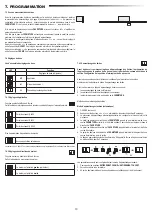
Page 10: ...hold P button for 5 seconds to enter the menu AP on the display indicates the first available function in menu 2 Use and buttons to navigate between the functions 3 Press P button to select the requir...

Page 11: ...ication Settings Sliding gate SL400 Sliding gate SL600 Sliding gate SL1000 More settings available on demand No application selected Available Learning methods Before starting a Learning phase ensure...

Page 12: ...force Starting position of the Soft Stop NOTE To stop Learning phase press S button The Learning process will be interrupted LE will flash on LED display After 5 seconds LL will appear on display indi...

Page 13: ...IRs is mandatory for myQ operation 2 Create an account Download the free myQ App from App Store or Google Play Store and create an account If you already have an account use your username and password...

Page 14: ...and 03 TTC timer will be overridden by an Input command and will CLOSE the gate Under setting 06 active TTC timer count down will be re set to start again by an Input command IR active on CLOSE moveme...

Page 15: ...behaviour is valid both for motor force detection and safety edge application 1 5 m opening travel 2 m opening travel default 3 m opening travel 7 7 5 Partial Opening Partial opening only gives you th...

Page 16: ...assword can t be accessed if the new password is not set Password will be required to change protected Functions after the setup No password selected Default Selection available ATTENTION Any changes...

Page 17: ...standard speed as per default setting Standard speed change impacts the Soft Stop speed Password must be entered to access this function Standard speed Default 10 20 30 50 10 20 7 8 Factory Default 7...

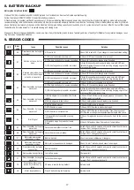
Page 18: ...is shorted out or reverse connected 2 Check IR3 connection change wires if needed 3 IR3 is not aligned or blocked for a moment 3 Align IR transmitter and receiver to make sure both LED is on instead o...

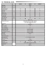
Page 19: ...RX 868MHz 868 30MHz 868 95MHz 869 85MHz TX 865 125MHz 865 829MHz 866 587MHz 10 mW Code Security 2 0 Max nr of remotes 180 Max nr of keypads 4 Max nr of myQ devices 16 External accessory power 24VDC m...

Page 20: ...ur statutory rights are not affected by this manufacturer s warranty Please see www liftmaster eu for terms of warranty Our electrical and electronic equipment may not be disposed of with household wa...

Page 21: ...mites 10 7 5 Mode veille 11 7 6 Programmation et suppression des t l commandes accessoires radio et appareils myQ 12 7 7 R glages avanc s 13 7 7 1 Vue d ensemble r glages avanc s 13 7 7 2 R glages de...

Page 22: ...blessure corporelle ou tout dommage mat riel Veuillez lire ces instructions attentivement Symboles d avertissement Le symbole g n ral d avertissement indique un danger pouvant entra ner des blessures...

Page 23: ...automatisme de la porte est r gl correctement Personne ne doit passer dans la zone du portail pendant qu il est en mouvement Les enfants ne doivent pas tre autoris s jouer proximit du portail La prote...

Page 24: ...2x T l commandes 2x Manuel d installation 1 2 3 3 4 5 4 1 Unit moteur avec panneau de commande 2 Cr maill re 3 Boucles magn tiques 4 Cellules photo lectriques infrarouge 5 Lampe clignotante 8 13 mm 8...

Page 25: ...depuis le bas Fixez par dessus l aide d un deuxi me crou 2 Recommencez pour les 3 autres vis d ancrage voir l image 3 3 Passez les c bles pr par s voir l image 4 travers le trou de la plaque de base 4...

Page 26: ...parsoudure acieruniquement ou l aidedevis voirl image9 Placezlepremiersegmentdelacr maill re l extr mit duportailpourqu ellesoit reli e au pignon de l automatisme comme illustr sur l image 10 et fixez...

Page 27: ...la position Ferm du c t oppos du portail 7 Une fois qu il est atteint la section du segment num rique en bas droite de l cran est activ e 8 Si n cessaire ajustez la position de l aimant v rifiez que l...

Page 28: ...p Fully Open Partial Open LAMP 1 FLASH LAMP SE SE GND GND IR3 IN3 IN2 IN1 IR2 IR1 L L N N PE AC 230V IN CTRL GND 12V TX RX 5V OP CL 24V external accessories Examples external receiver 220 240V 50 60Hz...

Page 29: ...nt connect s 1 Appuyez sur le bouton P et maintenez le enfonc pendant 5 secondes pour entrer dans le menu AP l cran indique la premi re fonction disponible dans le menu 2 Utilisez les boutons et pour...

Page 30: ...bles sur demande Aucune application s lectionn e M thodes d apprentissage disponibles Avant de d marrer une phase d apprentissage assurez vous que 1 les autres r glages de base sont termin s 2 les aim...

Page 31: ...EMENT OUVERT Force d ouverture et de fermeture Position de d part de l arr t en douceur REMARQUE pour arr ter la phase d apprentissage appuyez sur le bouton S Le processus d apprentissage s interrompt...

Page 32: ...gez l appli gratuite myQ depuis l App Store ou le Google Play Store et cr ez un compte Si vous avez d j un compte utilisez votre nom d utilisateur et votre mot de passe 3 Enregistrer la passerelle int...

Page 33: ...param tres 01 02 et 03 la minuterie TTC est cras e par une commande d entr e et FERME le portail Avec le param tre 06 le compte rebours de la minuterie TTC actif est r initialis par une commande d en...

Page 34: ...t valable tant pour la d tection de la force du moteur que pour l application de but e de s curit Distance d ouverture 1 5 m Distance d ouverture 2 m par d faut Distance d ouverture 3 m 7 7 5 Ouvertur...

Page 35: ...sse ne sont pas accessibles tant que le nouveau mot de passe n est pas configur Le mot de passe sera demand pour changer les fonctions prot g es apr s la configuration Aucun mot de passe s lectionn pa...

Page 36: ...onction r glages d usine r initialise le panneau de commande aux param tres d usine originaux Touslesparam tres ycomprislesparam tresdefindecourse sontsupprim s L cranLEDaffiche E0 Les t l commandes p...

Page 37: ...ED sont allum es au lieu de clignoter S assurer que rien ne pend sur le portail qui pourrait entraver ponctuellement l IR E4 Lorsqu on appuie sur l metteur le portail ne se d place pas 1 La but e de s...

Page 38: ...8 30 MHz 868 95 MHz 869 85 MHz TX 865 125 MHz 865 829 MHz 866 587 MHz 10 mW Code Security 2 0 Nombre max de t l commandes 180 Nombre max de claviers 4 Nombre max d appareils myQ 16 Puissance des acces...

Page 39: ...Ne tenez pas compte des instructions de configuration Vos droits statutaires ne sont pas remis en cause par cette garantie du fabricant Veuillez consulter www liftmaster eu pour conna tre les conditio...

Page 40: ...6 Programmeren en wissen van afstandsbedieningen radioaccessoires en myQ apparaten 12 7 7 Geavanceerde instellingen 13 7 7 1 Overzicht geavanceerde instellingen 13 7 7 2 Zenderinstellingen 13 7 7 3 I...

Page 41: ...ersoonlijk letsel of schade aan eigendommen te voorkomen Lees deze instructies zorgvuldig Waarschuwingssymbolen Het algemene waarschuwingssymbool wijst op een gevaar dat kan leiden tot letsel of de do...

Page 42: ...orden gebruikt als de gebruiker het hele poortgebied kan overzien en er zeker van is dat het vrij is van obstakels en dat de poortopener juist is ingesteld Niemand mag door het poortgebied terwijl het...

Page 43: ...ntgrendelingssleutel 2x Afstandsbediening 2x Installatiehandleiding 1 2 3 3 4 5 4 1 Motor met bedieningspaneel 2 Rek 3 Magneetbeugels 4 Infrarood fotocellen 5 Knipperlicht 8 13 mm 8 13 mm 2 LEVERINGSO...

Page 44: ...derkant in de grondplaat Zet van bovenaf vast met een tweede moer 2 Herhaal dit voor de resterende 3 ankerschroeven zie afbeelding 3 3 Haal de voorbereide kabels zie afbeelding 4 door het gat in de gr...

Page 45: ...in de GESLOTEN positie 2 Het stalen of nylon rek kan worden bevestigd door middel van lassen alleen staal of met schroeven zie afbeelding 9 Plaats het eerste reksegment aan het uiteinde van de poort...

Page 46: ...kant van de poort is bevestigd 7 Wanneer dit bereikt is zal het gedeelte van de rechter digitale onderzijde van de display oplichten 8 Pas zo nodig de positie van de magneet aan controleer of de digi...

Page 47: ...NO NO Stop Fully Open Partial Open LAMP 1 FLASH LAMP SE SE GND GND IR3 IN3 IN2 IN1 IR2 IR1 L L N N PE AC 230V IN CTRL GND 12V TX RX 5V OP CL 24V external accessories Examples external receiver 220 240...

Page 48: ...enen AP op het display geeft de eerste beschikbare functie in het menu aan 2 Gebruik de knoppen en om tussen de functies te navigeren 3 Druk op de knop P om de gewenste functie te selecteren 4 De stan...

Page 49: ...nstellingen Schuifpoort SL400 Schuifpoort SL600 Schuifpoort SL1 000 Meer instellingen beschikbaar op aanvraag Geen toepassing geselecteerd Beschikbare leermethoden Alvorens een leerfase te beginnen zo...

Page 50: ...Openings en sluitingskracht Startpositie van de soft stop OPMERKING Om de leerfase te stoppen drukt u op de knop S Het leerproces wordt onderbroken LE knippert op het led display Na 5 seconden versch...

Page 51: ...2 Cre er een account Download de gratis myQ app uit de App Store of Google Play Store en cre er een account Als u al een account heeft gebruik dan uw gebruikersnaam en wachtwoord 3 Registreer de myQ...

Page 52: ...zal de poort SLUITEN Onder instelling 06 wordt het aftellen van de actieve TTC timer opnieuw ingesteld om opnieuw te starten door een invoercommando IR actief bij beweging SLUITEN Als de IR straal wor...

Page 53: ...gsslag van 1 5 m Openingsslag van 2 m standaard Openingsslag van 3 m 7 7 5 Gedeeltelijke opening Gedeeltelijke opening geeft u de mogelijkheid om de actieve vleugel slechts tot een vooraf ingestelde w...

Page 54: ...beveiligd zijn niet toegankelijk als het nieuwe wachtwoord niet is ingesteld Een wachtwoord is nodig om beschermde functies te wijzigen na de instelling Geen wachtwoord geselecteerd standaard Selecti...

Page 55: ...is 50 van de standaardsnelheid zoals standaard ingesteld De standaard snelheidsverandering heeft invloed op de soft stopsnelheid Voor toegang tot deze functie moet een wachtwoord worden ingevoerd Stan...

Page 56: ...rd 3 Lijn de IR zender en ontvanger uit om er zeker van te zijn dat beide leds aan zijn in plaats van te knipperen Zorg ervoor dat er niets aan de poort hangt dat op korte termijn de IR blokkering kan...

Page 57: ...85 MHz TX 865 125 MHz 865 829 MHz 866 587 MHz 10 mW Code Security 2 0 Max aantal afstandsbedieningen 180 Max nr toetsenborden 4 Max aantal myQ apparaten 16 Vermogen externe accessoires 24 VDC max 500...

Page 58: ...ties Uw wettelijke rechten worden door deze fabrieksgarantie niet aangetast Zie www liftmaster eu voor de garantievoorwaarden Onze elektrische en elektronische apparatuur mag niet met het huisvuil wor...

Page 59: ...Chamberlain GmbH Saar Lor Lux Str 19 66115 Saarbr cken Germany WEEE Reg Nr DE66256568 www liftmaster eu info liftmaster eu 2021 all rights reserved 114A5443...

Reviews: