background image

3

During operation, the gate should not under any circumstances obstruct public path ways and roads (public area).

When using tools and small parts to install or carry out repair work on a gate exercise caution and do not wear rings, watches or loose clothing.

To avoid serious personal injury due to entrapments, remove any locking device fitted to the gate in order to prevent damage to the gate.

Installation and wiring must be in compliance with your local building and electrical installation regulations. Power cables must only be connected to a properly earthed 

supply.

Disconnect electric power to the system before installation, maintenance, repairs or removing covers.  A disconnecting device must be provided to the mains power supply 

(permanently-wired installation) to guarantee all-pole disconnection (isolating switch or by a separate fuse). The repairs and electrical installations may be performed only 

by an authorised electrician. Emergency Stop Button must be installed for emergency case based on the risk assessment.

Ensure that entrapment between the driven part and the surrounding fixed parts due to the opening movement of the driven part is avoided by respecting the given safety 

distances in accordance with the EU: EN 13241, EN12604, EN 12453, EN 12635; GB (UK, NI) BS EN 13241, BS EN12604, BS EN 12453, BS EN12635 and/or with 

safety devices (e.g. safety edge).

Testing of the safety function of the drive system is recommended to be carried out at least once a month. Refer also to manufacturers instruction of the gate system 

components. 

After the installation a final test of the full function of the system and the of the safety devices must be made and all users must be instructed in the function and operation 

of the sliding gate operator.

Gate systems must meet the force limitation according EU: EN 12453, EN 60335-2-103; GB (UK, NI) BS EN 12453, BS EN 60335-2-103. 

Additional safety device (safety edge,.) must be considered in accordance to the standard by changes to the system.

It is important to make sure that the gate always runs smoothly. Gates which stick or jam must be repaired immediately. Employ a qualified technician to repair the 

gate, never attempt to repair it yourself. This device is not intended for use by persons (including children) with restricted physical, sensory or mental abilities or lack of 

experience or knowledge, unless they are supervised by a person responsible for their safety or have received instruction in how to use the device. If necessary, control 

equipment MUST be mounted within sight of the gate and out of reach of children. Children should be supervised to ensure that they do not play with the device. Do not 

allow children to operate push button(s) or remote(s). Misuse of the gate operator system can result in serious injury. 

The warning signs should be placed in clearly visible locations.

The gate opener should ONLY be used if the user can see the entire gate area and is assured that it is free of obstacles and the gate operator is set correctly. No one may 

pass through the gate area while it is moving. Children must not be allowed to play in the vicinity of the gate.

The full protection against potential crushing or entrapment must work immediately when the drive arms are installed.

There may be existing hazards on mechanical, electrical installation or the closing edges of the gate by crushing, impact points:

• 

Structural failure, leaf, hinges, fixings, travel stops, wind load

• 

Crush, hinge area, under the gate, safety distance on fixed object

•  Electrical failure (Control – faults in safety systems)

•  Impact, swept area, hold to run, force limitation, presence detection

Appropriate measures must be taken to ensure safe operation of the gate system according the standards.

Never start up a damaged drive.

Use the manual release only to disengage the drive and – if possible – ONLY when is gate closed. Operation of the emergency manual release can lead to uncontrolled 

movements of the gate.  The Timer-to-Close (TTC) feature, the myQ Smartphone Control app, are examples of unattended operation of the gate. 

Any device or feature that allows the gate to close without being in the line of sight of the gate is considered as unattended open/close. 

The Timer-to-Close (TTC) feature, the myQ Smartphone Control, and any other myQ devices can ONLY be activated when Liftmasters photo cells are installed (TTC 

works only in close direction). The gate shall only be operated in the direct sight line to the gate.

IMPORTANT INFORMATION!

• 

This procedure is also required on private installations (new or retrofitted to a manually operated gate).


This installation and operating manual must be retained by the user.

•  The manufacturer accepts no liability/warranty claims resulting from use other than intended use and after the warranty expires.

•  The legal remedy is the sole responsibility for all associated rights.

NOTE:

 Observe the installation and operating manual.

•  Always monitor the function of the system and rectify the cause immediately in the event of a malfunction.

•  Carry out an annual inspection of the system. Call a specialist.

•  Safety distances must be respected between the gate leaf and the environment in accordance with related standards.

•  The operator can be installed Only on stable and rigid gate leaves. Gate leaves must not bend or twist when opening and closing.

•  Assure that the hinges of the gate leaf are installed and working correctly and not creating any obstacles.

•  Installation of two operators on same door leaf is strictly prohibited.

• 

Observe the corresponding requirements of the local, national regulations for compliance with the measures to protect human health, which must be observed when 

contacting other people, including employees, suppliers and customers (e.g. safety distance, mask requirement, etc).

• 

Precise information can be requested from the local authorities. 

1. SAFETY INSTRUCTIONS AND INTENDED USE

Summary of Contents for LiftMaster SL1000EVK

Page 1: ...Operator Installation Manual fr Manuel d installation de l op rateur de portail coulissant nl Installatiehandleiding schuifhekaandrijving For GB UK NI specific information on national regulations and...

Page 2: ...Learning 10 7 5 Stand by Mode 11 7 6 Programming and Erasing of Remote Controls Radio Accessories and myQ Devices 12 7 7 Advanced Settings 13 7 7 1 Overview Advanced Settings 13 7 7 2 Transmitter Set...

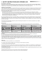
Page 3: ...tions to avoid personal injury or damage to property Read these instructions carefully Warnings Symbols The general warning symbol indicates a danger that can lead to injuries or death In the text sec...

Page 4: ...le locations The gate opener should ONLY be used if the user can see the entire gate area and is assured that it is free of obstacles and the gate operator is set correctly No one may pass through the...

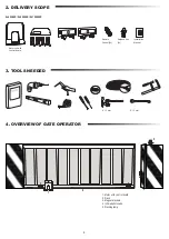
Page 5: ...control board Release Key 2x Remote Control 2x Installation Manual 1 2 3 3 4 5 4 1 Motor with control board 2 Rack 3 Magnet brackets 4 Infrared photocells 5 Flashing lamp 8 13 mm 8 13 mm 2 DELIVERY SC...

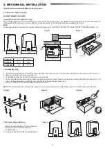
Page 6: ...Add a washer and insert it from the bottom into base plate Secure from top with a second nut 2 Repeat for remaining 3 anchor screws see picture 3 3 Get the prepared cables see picture 4 through the ho...

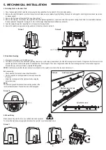
Page 7: ...el or nylon rack can be attached by welding steel only or with screws see picture 9 Put the first rack segment at the end of the gate so that it connects to the operator sprocket as shown in the pictu...

Page 8: ...se position on the opposite side of the gate 7 When reached section of the lower right digital on display will be on 8 If needed adjust the position of the magnet verify that the lower right digital w...

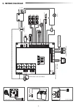
Page 9: ...OR 2 WHT GRN RED WHT GRN RED MOTOR 1 M CN4 BAT BAT 24V BATTERY POW 24V SPEC 24VDC SYNC STBY UART LIMIT SW E LK FLA COMMAND IR SENSOR EDGE 24V BAT 8 2K SAFETY EDGE NC NO NO Stop Fully Open Partial Open...

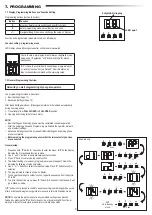
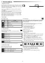
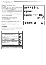
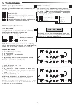
Page 10: ...hold P button for 5 seconds to enter the menu AP on the display indicates the first available function in menu 2 Use and buttons to navigate between the functions 3 Press P button to select the requir...

Page 11: ...ication Settings Sliding gate SL400 Sliding gate SL600 Sliding gate SL1000 More settings available on demand No application selected Available Learning methods Before starting a Learning phase ensure...

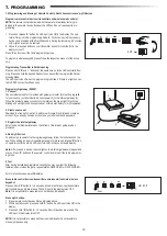
Page 12: ...force Starting position of the Soft Stop NOTE To stop Learning phase press S button The Learning process will be interrupted LE will flash on LED display After 5 seconds LL will appear on display indi...

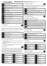
Page 13: ...IRs is mandatory for myQ operation 2 Create an account Download the free myQ App from App Store or Google Play Store and create an account If you already have an account use your username and password...

Page 14: ...and 03 TTC timer will be overridden by an Input command and will CLOSE the gate Under setting 06 active TTC timer count down will be re set to start again by an Input command IR active on CLOSE moveme...

Page 15: ...behaviour is valid both for motor force detection and safety edge application 1 5 m opening travel 2 m opening travel default 3 m opening travel 7 7 5 Partial Opening Partial opening only gives you th...

Page 16: ...assword can t be accessed if the new password is not set Password will be required to change protected Functions after the setup No password selected Default Selection available ATTENTION Any changes...

Page 17: ...standard speed as per default setting Standard speed change impacts the Soft Stop speed Password must be entered to access this function Standard speed Default 10 20 30 50 10 20 7 8 Factory Default 7...

Page 18: ...is shorted out or reverse connected 2 Check IR3 connection change wires if needed 3 IR3 is not aligned or blocked for a moment 3 Align IR transmitter and receiver to make sure both LED is on instead o...

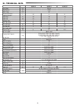
Page 19: ...RX 868MHz 868 30MHz 868 95MHz 869 85MHz TX 865 125MHz 865 829MHz 866 587MHz 10 mW Code Security 2 0 Max nr of remotes 180 Max nr of keypads 4 Max nr of myQ devices 16 External accessory power 24VDC m...

Page 20: ...ur statutory rights are not affected by this manufacturer s warranty Please see www liftmaster eu for terms of warranty Our electrical and electronic equipment may not be disposed of with household wa...

Page 21: ...mites 10 7 5 Mode veille 11 7 6 Programmation et suppression des t l commandes accessoires radio et appareils myQ 12 7 7 R glages avanc s 13 7 7 1 Vue d ensemble r glages avanc s 13 7 7 2 R glages de...

Page 22: ...blessure corporelle ou tout dommage mat riel Veuillez lire ces instructions attentivement Symboles d avertissement Le symbole g n ral d avertissement indique un danger pouvant entra ner des blessures...

Page 23: ...automatisme de la porte est r gl correctement Personne ne doit passer dans la zone du portail pendant qu il est en mouvement Les enfants ne doivent pas tre autoris s jouer proximit du portail La prote...

Page 24: ...2x T l commandes 2x Manuel d installation 1 2 3 3 4 5 4 1 Unit moteur avec panneau de commande 2 Cr maill re 3 Boucles magn tiques 4 Cellules photo lectriques infrarouge 5 Lampe clignotante 8 13 mm 8...

Page 25: ...depuis le bas Fixez par dessus l aide d un deuxi me crou 2 Recommencez pour les 3 autres vis d ancrage voir l image 3 3 Passez les c bles pr par s voir l image 4 travers le trou de la plaque de base 4...

Page 26: ...parsoudure acieruniquement ou l aidedevis voirl image9 Placezlepremiersegmentdelacr maill re l extr mit duportailpourqu ellesoit reli e au pignon de l automatisme comme illustr sur l image 10 et fixez...

Page 27: ...la position Ferm du c t oppos du portail 7 Une fois qu il est atteint la section du segment num rique en bas droite de l cran est activ e 8 Si n cessaire ajustez la position de l aimant v rifiez que l...

Page 28: ...p Fully Open Partial Open LAMP 1 FLASH LAMP SE SE GND GND IR3 IN3 IN2 IN1 IR2 IR1 L L N N PE AC 230V IN CTRL GND 12V TX RX 5V OP CL 24V external accessories Examples external receiver 220 240V 50 60Hz...

Page 29: ...nt connect s 1 Appuyez sur le bouton P et maintenez le enfonc pendant 5 secondes pour entrer dans le menu AP l cran indique la premi re fonction disponible dans le menu 2 Utilisez les boutons et pour...

Page 30: ...bles sur demande Aucune application s lectionn e M thodes d apprentissage disponibles Avant de d marrer une phase d apprentissage assurez vous que 1 les autres r glages de base sont termin s 2 les aim...

Page 31: ...EMENT OUVERT Force d ouverture et de fermeture Position de d part de l arr t en douceur REMARQUE pour arr ter la phase d apprentissage appuyez sur le bouton S Le processus d apprentissage s interrompt...

Page 32: ...gez l appli gratuite myQ depuis l App Store ou le Google Play Store et cr ez un compte Si vous avez d j un compte utilisez votre nom d utilisateur et votre mot de passe 3 Enregistrer la passerelle int...

Page 33: ...param tres 01 02 et 03 la minuterie TTC est cras e par une commande d entr e et FERME le portail Avec le param tre 06 le compte rebours de la minuterie TTC actif est r initialis par une commande d en...

Page 34: ...t valable tant pour la d tection de la force du moteur que pour l application de but e de s curit Distance d ouverture 1 5 m Distance d ouverture 2 m par d faut Distance d ouverture 3 m 7 7 5 Ouvertur...

Page 35: ...sse ne sont pas accessibles tant que le nouveau mot de passe n est pas configur Le mot de passe sera demand pour changer les fonctions prot g es apr s la configuration Aucun mot de passe s lectionn pa...

Page 36: ...onction r glages d usine r initialise le panneau de commande aux param tres d usine originaux Touslesparam tres ycomprislesparam tresdefindecourse sontsupprim s L cranLEDaffiche E0 Les t l commandes p...

Page 37: ...ED sont allum es au lieu de clignoter S assurer que rien ne pend sur le portail qui pourrait entraver ponctuellement l IR E4 Lorsqu on appuie sur l metteur le portail ne se d place pas 1 La but e de s...

Page 38: ...8 30 MHz 868 95 MHz 869 85 MHz TX 865 125 MHz 865 829 MHz 866 587 MHz 10 mW Code Security 2 0 Nombre max de t l commandes 180 Nombre max de claviers 4 Nombre max d appareils myQ 16 Puissance des acces...

Page 39: ...Ne tenez pas compte des instructions de configuration Vos droits statutaires ne sont pas remis en cause par cette garantie du fabricant Veuillez consulter www liftmaster eu pour conna tre les conditio...

Page 40: ...6 Programmeren en wissen van afstandsbedieningen radioaccessoires en myQ apparaten 12 7 7 Geavanceerde instellingen 13 7 7 1 Overzicht geavanceerde instellingen 13 7 7 2 Zenderinstellingen 13 7 7 3 I...

Page 41: ...ersoonlijk letsel of schade aan eigendommen te voorkomen Lees deze instructies zorgvuldig Waarschuwingssymbolen Het algemene waarschuwingssymbool wijst op een gevaar dat kan leiden tot letsel of de do...

Page 42: ...orden gebruikt als de gebruiker het hele poortgebied kan overzien en er zeker van is dat het vrij is van obstakels en dat de poortopener juist is ingesteld Niemand mag door het poortgebied terwijl het...

Page 43: ...ntgrendelingssleutel 2x Afstandsbediening 2x Installatiehandleiding 1 2 3 3 4 5 4 1 Motor met bedieningspaneel 2 Rek 3 Magneetbeugels 4 Infrarood fotocellen 5 Knipperlicht 8 13 mm 8 13 mm 2 LEVERINGSO...

Page 44: ...derkant in de grondplaat Zet van bovenaf vast met een tweede moer 2 Herhaal dit voor de resterende 3 ankerschroeven zie afbeelding 3 3 Haal de voorbereide kabels zie afbeelding 4 door het gat in de gr...

Page 45: ...in de GESLOTEN positie 2 Het stalen of nylon rek kan worden bevestigd door middel van lassen alleen staal of met schroeven zie afbeelding 9 Plaats het eerste reksegment aan het uiteinde van de poort...

Page 46: ...kant van de poort is bevestigd 7 Wanneer dit bereikt is zal het gedeelte van de rechter digitale onderzijde van de display oplichten 8 Pas zo nodig de positie van de magneet aan controleer of de digi...

Page 47: ...NO NO Stop Fully Open Partial Open LAMP 1 FLASH LAMP SE SE GND GND IR3 IN3 IN2 IN1 IR2 IR1 L L N N PE AC 230V IN CTRL GND 12V TX RX 5V OP CL 24V external accessories Examples external receiver 220 240...

Page 48: ...enen AP op het display geeft de eerste beschikbare functie in het menu aan 2 Gebruik de knoppen en om tussen de functies te navigeren 3 Druk op de knop P om de gewenste functie te selecteren 4 De stan...

Page 49: ...nstellingen Schuifpoort SL400 Schuifpoort SL600 Schuifpoort SL1 000 Meer instellingen beschikbaar op aanvraag Geen toepassing geselecteerd Beschikbare leermethoden Alvorens een leerfase te beginnen zo...

Page 50: ...Openings en sluitingskracht Startpositie van de soft stop OPMERKING Om de leerfase te stoppen drukt u op de knop S Het leerproces wordt onderbroken LE knippert op het led display Na 5 seconden versch...

Page 51: ...2 Cre er een account Download de gratis myQ app uit de App Store of Google Play Store en cre er een account Als u al een account heeft gebruik dan uw gebruikersnaam en wachtwoord 3 Registreer de myQ...

Page 52: ...zal de poort SLUITEN Onder instelling 06 wordt het aftellen van de actieve TTC timer opnieuw ingesteld om opnieuw te starten door een invoercommando IR actief bij beweging SLUITEN Als de IR straal wor...

Page 53: ...gsslag van 1 5 m Openingsslag van 2 m standaard Openingsslag van 3 m 7 7 5 Gedeeltelijke opening Gedeeltelijke opening geeft u de mogelijkheid om de actieve vleugel slechts tot een vooraf ingestelde w...

Page 54: ...beveiligd zijn niet toegankelijk als het nieuwe wachtwoord niet is ingesteld Een wachtwoord is nodig om beschermde functies te wijzigen na de instelling Geen wachtwoord geselecteerd standaard Selecti...

Page 55: ...is 50 van de standaardsnelheid zoals standaard ingesteld De standaard snelheidsverandering heeft invloed op de soft stopsnelheid Voor toegang tot deze functie moet een wachtwoord worden ingevoerd Stan...

Page 56: ...rd 3 Lijn de IR zender en ontvanger uit om er zeker van te zijn dat beide leds aan zijn in plaats van te knipperen Zorg ervoor dat er niets aan de poort hangt dat op korte termijn de IR blokkering kan...

Page 57: ...85 MHz TX 865 125 MHz 865 829 MHz 866 587 MHz 10 mW Code Security 2 0 Max aantal afstandsbedieningen 180 Max nr toetsenborden 4 Max aantal myQ apparaten 16 Vermogen externe accessoires 24 VDC max 500...

Page 58: ...ties Uw wettelijke rechten worden door deze fabrieksgarantie niet aangetast Zie www liftmaster eu voor de garantievoorwaarden Onze elektrische en elektronische apparatuur mag niet met het huisvuil wor...

Page 59: ...Chamberlain GmbH Saar Lor Lux Str 19 66115 Saarbr cken Germany WEEE Reg Nr DE66256568 www liftmaster eu info liftmaster eu 2021 all rights reserved 114A5443...

Reviews: