6
1.
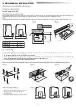
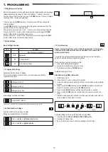
Once the base plate is fixed, raise the nut securing the base plate from the top about 5-10 mm and add a washer.
2. Remove the small front plastic cover from the operator and make a manual release by putting the key into keyhole, turning right and pulling the lever down (see manu-
al release page
5).
3. Remove the 2 screws on the sides of the cover (see picture 7).
4. Remove the Operator cover and put the operator on the base plate using the anchor screws and hole in the operator hosuing. Note: there must be distance between
the base plate and the operator hosuing (5-10 mm) for later height adjsutments possibilities (see picture 8).
5. Feed the cables through the repsective hole in the operator housing bottom.
6. Secure the operator using washer, spring washer and the nut as shown in picture 8.
5.4 Installing Motor on the Base Plate
max. 10 mm
Picture 8
Picture 7
5. MECHANICAL INSTALLATION
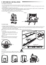
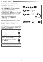
1. Manually move the gate into CLOSED position.
2.
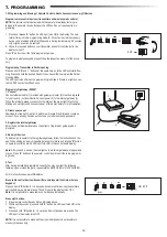
The steel or nylon rack can be attached by welding (steel only) or with screws (see picture 9). Put the first rack segment at the end of the gate so that it connects to the
operator sprocket as shown in the picture 10 and attach the rack to the gate. Then move the gate and attach the next rack segment near to the previous segment.
Proceed this way until you will reach complete OPEN position.
NOTE:
At all times consider that the rack does not complietly lie on the operator sprocket or has too much distance to it.
5.5 Gate Rack Mounting
Steel Rack (welding)
Steel Rack assembly help
2-3 mm
Before assembly:
•
Check whether the required screw-in depth available.
• Use the supplied connecting elements (screws) to assemble
the racks.
• Attach the rack segment at the right position by using the
delivered screws.
NOTE:
The material type and thickness at the mounting position of the
rack must be considered. The operator must be disengaged.
Picture 10
Picture 9
Nylon Rack to screw
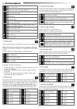
Mains power wiring must be done by a certified electrician specialist.
To connect the mains power supply please remove the operator cover as described above.
5.6 Power Wiring
Picture 11


