background image


HD2011NMT 

-   15   -

 V1.2


5


MEASUREMENTS 

The following table shows the available sound level meter measurement parameters.  


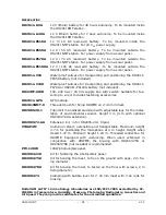
REAL 

TIME 

INTEGRATION 

TIME 

PARAMETERS


No 

1/32 s 

1 “Short” Lx,eq  

x = A, C or Z 

Yes 1/8 

1 selectable

parameter: 


 Lxyp 


 Lxpk 


 “short” Lx,eq 

1) Only LAFp for HD2010UC 

and HD2010UC/A 

 
x = A, C or Z; y = F, S or I 

x = A or C 

x = A, C or Z 

Yes 1/2 

5 selectable parameters: 

(3 for HD2010UC and 

HD2010UC/A): 


 Lxyp 


 Lxpk 


 “short” Lx,eq 


 Lx,eq 


x = A, C or Z; y = F, S or I 

x = A or C 

x = A, C or Z 

x = A, C or Z 

TIME 

HISTORY 

Yes  

Third octave spectrum 

16 Hz ÷ 20 kHz (25 Hz÷ 

12.5 kHz for HD2010UC 

and HD2010UC/A) 

Weighting LIN, FAST or 

SLOW 

No 

1s ÷ 1h 

5 selectable parameters: 


 Lxyp,max 


 Lxyp,min 


 Lxpk,max 


 Lxpk,min 


 Lx,eq 


 L1 ÷ L4 


 Overload 

 
x = A, C or Z; y = F, S or I 

x = A, C or Z; y = F, S or I 

x = A or C 

x = A or C 

x = A, C or Z 

1% ÷ 99% 

No  

Third octave spectrum 

16 Hz ÷ 20 kHz (25 Hz÷ 

12.5 kHz for HD2010UC 

and HD2010UC/A) 

Weighting LIN 

REPORTS 

No  

Statistics 

distribution 


No Event 

duration 

5 selectable parameters: 


 Lxyp,max 


 Lxyp,min 


 Lxpk,max 


 Lxpk,min 


 Lx,eq 


 L1 ÷ L4 


 Overload  

 
x = A, C or Z; y = F, S or I 

x = A, C or Z; y = F, S or I 

x = A or C 

x = A or C 

x = A, C or Z 

1% ÷ 99% 

No  

Third octave spectrum 

16 Hz ÷ 20 kHz (25 Hz÷ 

12.5 kHz for HD2010UC 

and HD2010UC/A) 

Weighting LIN 

EVENTS 

No  

Statistics 

distribution 


The choice of the measurements to be acquired and acquisition mode is carried out 

with the help of Noise Studio software (see the instructions of the software for de-
tails). 
The acquisition of sound level parameters can be: 

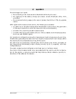
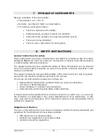
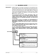
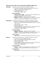
Summary of Contents for HD2011NMT

Page 1: ...Operating manual Noise Monitoring Terminal HD2011NMT www deltaohm com Companies Brands of GHM English Keep for future reference ...

Page 2: ... 2 FIXING THE HOUSING MODELS HD2011NMT BXX TO THE MAST OR TRIPOD 9 4 3 INSTALLATION OF THE SOLAR PANEL MODELS HD2011NMT XXP 9 4 4 POSITIONING THE MICROPHONE UNIT 10 4 5 CONNECTIONS 11 4 6 POSITIONING THE 3G ANTENNA 12 4 7 INSERTING THE SIM CARD 13 5 MEASUREMENTS 15 6 ALARMS 17 7 STORAGE OF INSTRUMENTS 18 8 SAFETY INSTRUCTIONS 18 9 ORDERING CODES 19 ...

Page 3: ...out the mea surements or transmit the data so as to considerably prolong the life of the battery The station can be remotely controlled via the Monitor module of the Noise Studio program The program installable on any PC with a Windows operating system al lows you to configure all the measurement parameters and the data storage and dis plays the measurements in graphic and tabular form Besides the...

Page 4: ...HD2011NMT 4 V1 2 2 DESCRIPTION ...

Page 5: ...olling the station is op erational CHARGE LED indicates that the battery is being charged BATTERY LEVEL LEDs indicate the battery charge level o All LEDs off low battery o 1 LED on charge is less than 25 o 2 LEDs on charge is between 25 and 50 o 3 LEDs on charge is between 50 and 75 o 4 LEDs on charge is more than 75 POWER LED indicates the presence of the internal power supply 12 VDC of the batte...

Page 6: ...elative humidity and temperature probe of a rain gauge and of an anemometer RS485 port with Master MODBUS RTU protocol for the connection of an external weather station Connection to PC 3G GPRS TCP IP connection via the 3G GSM modem Alarms 1 potential free contact isolated alarm output Normally open contact max 300 mA 30 Vdc resistive charge Sending of alarms via e mail Operational conditions 20 5...

Page 7: ...an be switched on and off by using the ON OFF switch Afetr switching on wait for the functional check and the initial automatic configuration with the server to be completed During the functional check the sound level meter is switched on for a couple of minutes and then switched off after the server has rec ognized the station At the end the NETWORK CONNECTION LED must light up If the sound level...

Page 8: ...t After sending the SMS the station must be switched off and back on with the ON OFF switch 4 1 INSTALLATION OF THE HD2005 20 1 TRIPOD Pull out the tripod from the bag and open it by turning the three legs Secure the legs to the central block of the tri pod The inclination of the legs can be adjusted using the various holes available Adjust the height of the legs and tighten the locking screw The ...

Page 9: ...THE SOLAR PANEL MODELS HD2011NMT XXP Fix the support of the solar panel to the mast or tripod then fix the solar panel to the support The solar panel must be ori ented towards the SOUTH in the northern hemisphere and towards the NORTH in the southern hemisphere The solar panel must not be overshadowed by trees or buildings nearby Solar panel Support of the solar panel HD2011NMT ...

Page 10: ...e connecting cable inside the tube Mobile installation with box placed on the floor and microphone unit placed on the extensibile VTRAP4M stand Fixed installation with HD2005 20 1 tripod The VTRAP4M stand is extensible and transportable it has 3 7 m maximum height for positioning the microphone at 4 m height The HD2005 20 1 tripod has 3 m maxi mum height extensible to 4 m with optional HD2003 72 A...

Page 11: ...ector for connecting the charger The connector can be located at the bottom of the housing BATTERY CHARGER label or inside the housing depending on the type of battery used The following image shows the inputs layout in a model without optional inputs outputs and powered by a li thium battery with 48h autonomy In the models powered by a solar panel or 24 VDC source pass the power cable through the...

Page 12: ...ing rod on the top of the mast or tripod The lightning rod must be electrically insulated from the mast tripod and must be properly connected to ground rods 4 6 POSITIONING THE 3G ANTENNA Place the 3G antenna on top of the housing protection shield A metal plate is positioned under the upper and back left corner of the shield in order to hold the magnetic base of the antenna in place 3G antenna po...

Page 13: ...n ON OFF switch to OFF 2 Open the Velcro strap that tightens the sound level meter and remove the sound level meter 3 After removing the sound level meter the opening to access the modem is visible The modem is located on the left side of the opening 4 Press with a pointed object the release button of the SIM tray and extract the tray Insert the SIM card into its tray the SIM card contacts must fa...

Page 14: ...work 1 Switch on the station ON OFF switch to ON 2 Send to the phone number of the SIM inserted in the station an SMS with the fol lowing text password APN name reset With password last 6 digits of the modem serial number name name of the APN provided by the phone operator Example 256155 APN internet operator reset 3 Switch the station off and back on with the ON OFF switch SIM tray release button...

Page 15: ...ctable parameters Lxyp max Lxyp min Lxpk max Lxpk min Lx eq L1 L4 Overload x A C or Z y F S or I x A C or Z y F S or I x A or C x A or C x A C or Z 1 99 No Third octave spectrum 16 Hz 20 kHz 25 Hz 12 5 kHz for HD2010UC and HD2010UC A Weighting LIN REPORTS No Statistics distribution No Event duration 5 selectable parameters Lxyp max Lxyp min Lxpk max Lxpk min Lx eq L1 L4 Overload x A C or Z y F S o...

Page 16: ...he set duration At intervals the acquisition starts at the programmed date and time lasts for the set duration and is repeated at regular intervals In addition to the measurements acquisition an automatic calibration to be carried out at the beginning and or at the end of the acquisition or to be carried out at regu lar intervals can be programmed ...

Page 17: ...ated with one of the available environmental parame ters only with METEO option It is possible to configure how long the measurement must remain above the set thre shold before generating the alarm and how long the measurement must remain within the deactivation threshold before turning off the alarm The alarm can be reported by activating the alarm output only for the exceeding of the measurement...

Page 18: ...measures described in this manual are followed The regular functioning and operational safety of the instruments can only be guaran teed under the climatic conditions specified in the manual Do not use the instruments in places where there are Rapid ambient temperature variations that may cause condensation Corrosive or flammable gases Direct vibrations or bumps to the instrument High intensity el...

Page 19: ...d and the fixing accessories have to be specified separately The SIM card is not included The microphone must be compatible with HD2010PNE2W if HD2010UC or HD2010UC A sound level meter is ordered or HD2110PEWL if HD2110L sound level meter is ordered pre amplifier For the models HD2011NMT xxB please specify when order ing if you need the battery with 48 hours HD2011 Li9A or 7 days HD2011 Li40A auto...

Page 20: ...C 61260 Dynamic range 30 dB 140 dB Linear range 80 dB Spectral analysis by octave bands from 32 Hz to 8 kHz and op tionally third octave bands from 25 Hz to 12 5 kHz Pre amplifier HD2010PNE2W Required options Memory expansion doubles the memory capacity Monitor continuous data logging power supply via serial cable specific for operating with HD2011NMT monitoring stations Other options Third octave...

Page 21: ...fastening accessories HD2011 GPS GPS module HD2011NMT 9 Threaded bush for fixing HDWME on 40 mm mast HD2005 20 1 Tripod kit in anodized aluminum with adjustable legs for the instal lation of environmental sensors Height 3 m 4 m with optional HD2003 72 AA extension HD2003 72 AA Extension L 1 m for HD2005 20 1 tripod VTRAP4M Aluminum stand extensible and transportable Maximum height 3 7 m for positi...

Page 22: ...HD2011NMT 22 V1 2 NOTES ...

Page 23: ......

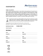
Page 24: ...zed third parties is excluded from the guarantee The instrument shall be returned FREE OF SHIPMENT CHARGES to your dealer The jurisdiction of Padua applies in any dispute The electrical and electronic equipment marked with this symbol cannot be disposed of in public landfills According to the Directive 2011 65 EU the european users of electrical and electronic equipment can return it to the dealer...

Page 25: ...he result of the constant development of the product This may produce some differences between the information written in this manual and the instrument you have purchased We cannot completely exclude the possibility of errors in the manual for which we apologize The data images and descriptions included in this manual cannot be legally asserted We reserve the right to make changes and corrections...

Page 26: ...GHM GROUP Delta OHM Delta Ohm S r l a socio unico Via Marconi 5 35030 Caselle di Selvazzano Padova ITALY Phone 39 049 8977150 Fax 39 049 635596 www deltaohm com info deltaohm com V1 2 12 09 2018 ...

Reviews: