background image

Fault finding with the display code 


F1

  Dry running. Shows when the pump has been started without water, press the 

up arrow button to start the pump again. 


F2

  Shows  excessive  temperature  inside  the  controller.  The  pump  performance  is 

automatically  reduced  to  prevent  any  damage.  After  the  source  of  the 
increased  temperature  has  been  removed,  the  pump  performance  can  be 
selected again with the up/down buttons. 


F3

   Starting  error.  If  the  pump  rotor  is  blocked,  the  pump  will  switched  off  after 

starting.  After  removal  of  the  blockage  the  pump  can  be  started  again  by 
disconnecting and reconnecting the pump from mains electricity. 


F4

  Rotor  blockage  during  operation.  Should  the  rotor  stop  during  normal 

operation  due  to  foreign  particles.  The  pump  switches  off  after  3  restarting 
attempts.  Remove  the  blockage  and  restart  (low  voltage)  the  pump  by 
disconnecting / reconnecting from mains electricity. 


F5

  If the local voltage is too low the pump will switch off automatically. 


F7


Init  Fault.  This  indicates  a  fault  in  the  controller.  It  may  be  possible  in  some 
cases  to  rectify  it  by  disconnecting  /  reconnecting  the  pump  from  mains 
electricity. If not the pump has to returned to Deltec for inspection. 


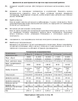
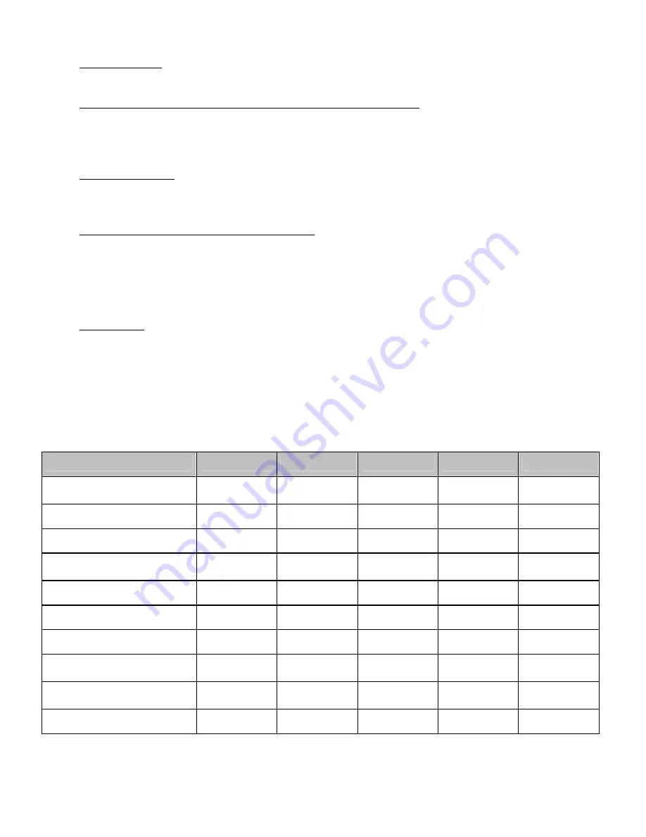
Technical Data 


technical data 

E-

Flow

 10 

E-

Flow

 12 

E-

Flow

 16 

E-

Flow

 R2 

E-

Flow

 R3 

volume max.  

9.000   

litre/h 

11.800 

litre/h 

14.000 

litre/h 

7.300   

litre/h 

8.000   

litre/h 

water head max. 

6,0 meters 

8,0 meters 

9,0 meters 

7,5 meters 

9,5 meters 

power consumption max. 

80 Watt 

130 Watt 

180 Watt 

80 Watt 

130 Watt 

performance selection 

electronic,        

7 stages 

electronic,      

12 stages 

electronic,      

17 stages 

electronic,        

7 stages 

electronic,      

12 stages 

voltage 

230/240 Volt  230/240 Volt  230/240 Volt  230/240 Volt  230/240 Volt 

inlet diameter 

40 mm  

40 mm  

50 mm  

32 mm  

40 mm  

outlet diameter 

32 mm  

40 mm  

40 mm 

25/32 mm  

32 mm  

dimensions pump  
(l/w/h) mm 

195x132x212  200x135x214  230x135x214  190x105x200  195x125x203 

dimensions controller 
(l/w/h) mm 

190x215x65  190x215x65  190x215x65  190x215x65  190x215x65 

weight 

3,50 kg 

3,60 kg 

3,90 kg 

3,50 kg 

3,60 kg 


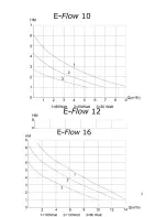
Flowcharts from page 26 


-11- 

Summary of Contents for E-Flow 10

Page 1: ...E Flow Pumps Bedienungsanleitung Operating instructions Instructions d utilisation Istruzioni per l uso...

Page 2: ...Auf diese Weise tropft das Wasser unter der Steckdose vom Kabel ab und kann nicht mit dieser in Ber hrung kommen Wenn der Stecker oder die Steckdose nass wird NICHT das Kabel herausziehen sondern die...

Page 3: ...itung an einem sicheren jederzeit zug nglichem Ort auf Bitte lesen Sie diese Anleitung sorgf ltig durch bevor Sie mit der Installation beginnen Sollten Sie trotzdem noch Fragen haben wenden Sie sich b...

Page 4: ...auf der Saugseite betreiben Einbau des Controllers Der Controller muss an einem trockenen gut bel fteten Platz angebracht werden gesch tzt vor Sonneneinstrahlung Beleuchtung und anderen W rmequellen...

Page 5: ...tztrennung eingestellt war Controller Panel Steuerger t 1 Remote rotes Licht Die Pumpe n k nnen mit einem optionalen Steuerger t ab April 2012 ausger stet werden Durch dieses Steuerger t hat die Pumpe...

Page 6: ...Fehler Wird angezeigt bei einem fehlerhaften Controller Eventuell einen Neustart der Pumpe durch Trennen und wieder einschalten vom Netz versuchen Ansonsten muss die Pumpe an den Hersteller eingeschi...

Page 7: ...in contact with the receptacle If the plug or socket does get wet DON T unplug the cord Disconnect the fuse or circuit breaker that supplies power to the appliance Then unplug and examine for presenc...

Page 8: ...s Please read the following instructions very carefully before installing the pump Should you still have questions please contact your supplier Installation of the pump Always unplug the pump during t...

Page 9: ...llation of the controller Install the controller in a dry suitably vented place away from water dampness and other heat sources like sunlight artificial light etc For optimum cooling effect of the con...

Page 10: ...n a interval or random mode Up to four pumps can be controlled with one multifunction controller If the multifunction controller is used the red light comes on 2 Green light It indicates that the powe...

Page 11: ...is too low the pump will switch off automatically F7 Init Fault This indicates a fault in the controller It may be possible in some cases to rectify it by disconnecting reconnecting the pump from main...

Page 12: ...devaient tre humides NE DECONNECTEZ PAS ceux ci D branchez au pr alable le fusible alimentant cet appareil D connectez ensuite la prise et examinez la pr sence ventuelle d eau dans la prise murale 12...

Page 13: ...en lieu s r et accessible en toute circonstance Lisez attentivement les instructions suivantes avant d installer la pompe En cas de question contactez votre revendeur Installation de la pompe Toujours...

Page 14: ...n partiellement ou totalement ferm e Installation du contr leur Installez le contr leur dans un endroit sec suffisamment a r l abri de l eau de l humidit et autre source de chaleur telle que le soleil...

Page 15: ...en mode al atoire ou intervalle Quatre pompes peuvent tre contr l es avec un seul contr leur multi fonctions Si le contr leur multi fonctions est utilis la lumi re rouge s allume 5 Lumi re verte Indi...

Page 16: ...i la tension locale est trop faible la pompe s teindra automatiquement F7 Erreur Init Cela indique un d faut au niveau du contr leur Dans certains cas un reset d connecter reconnecter peut s av rer ef...

Page 17: ...o la spina si bagna NON disinserire il cavo ma scollegare l interruttore generale che porta corrente all apparecchio Quindi scollegare la spina e verificare la presenza di acqua all interno della pre...

Page 18: ...rvare le presenti istruzioni in luogo sempre accessibile Leggere attentamente le istruzioni prima di iniziare l installazione Nel caso di dubbi e o domande rivolgersi al rivenditore o direttamente a D...

Page 19: ...annello di controllo Il pannello di controllo deve essere installato in un luogo asciutto ben ventilato al riparo dalla luce diretta del sole dall impianto di illuminazione e da altre fonti di calore...

Page 20: ...edenti l interruzione Pannello di controllo 5 Remote luce rossa La pompa pu essere fornita con un pannello di controllo opzionale a partire da Aprile 2012 Tramite tale pannello sar possibile attivare...

Page 21: ...la pompa dalla rete elettrica ricollegarla e quindi riavviarla F5 Indica che la tensione di rete locale estremamente bassa F7 Init Fault Indica un difetto nel pannello di controllo In alcuni casi suff...

Page 22: ...E FLOW Deltec E Flow up down E Flow Deltec E Box 30 Deltec E Flow 16 Deltec GmbH 22...

Page 23: ...2 32 40 300 2 3 30 0 0 UP 20 down 0 down 23...

Page 24: ...9 Remote 2012 10 11 e f F 12 UP DOWN 24...

Page 25: ...000 7 300 8 000 6 0 8 0 9 0 7 5 9 5 80 130 180 80 130 7 12 17 7 12 230 240 230 240 230 240 230 240 230 240 40 40 50 32 40 32 40 40 25 32 32 195x132x2 12 200x135x2 14 230x135x2 14 190x105x2 00 195x125...

Page 26: ......

Page 27: ...27...

Page 28: ...28 Deltec E BOX Die E Box ist ein multifunktionales E Flow Pumpen Steuerger t...

Page 29: ...ox kann f r alle E Flow Pumpen verwendet werden und wird komplett mit einem Netzteil und Steuerkabel geliefert Funktionen E Box Futtertimer Pumpentyp Intervall Sprache Zufall Kontrast Fernbedienung St...

Page 30: ...ion of pump type interval mode language random mode display brightness remote control Pump connection Aquarium computer Power adapter It comes with a power adapter and a connecting cable 2 m to the pu...

Page 31: ......
Page 32: ...Deltec GmbH Steller Stra e 75 D 27755 Delmenhorst Deutschland Germany www deltec aquaristic com Deltec GmbH 11 2013...

Reviews: