background image

Max. weight of gate

200 Kg

Max. width of gate

2,50 mt

Motors power supply

24Vdc

230 Vac

Motor power

50 W

200 W

Motor RPM

1800

1400

Condenser

/

12,5 µF

Mechanical unlock for emergency manoeuvre

With key

Working temperature

-20° C / +55° C

weight

8 Kg

Protection rating

IP 55

Opening time 90°

15 sec

Rod stroke

400 mm

Force of thrust

1500 N

Motor current input

1,5 A

1 A

2

5

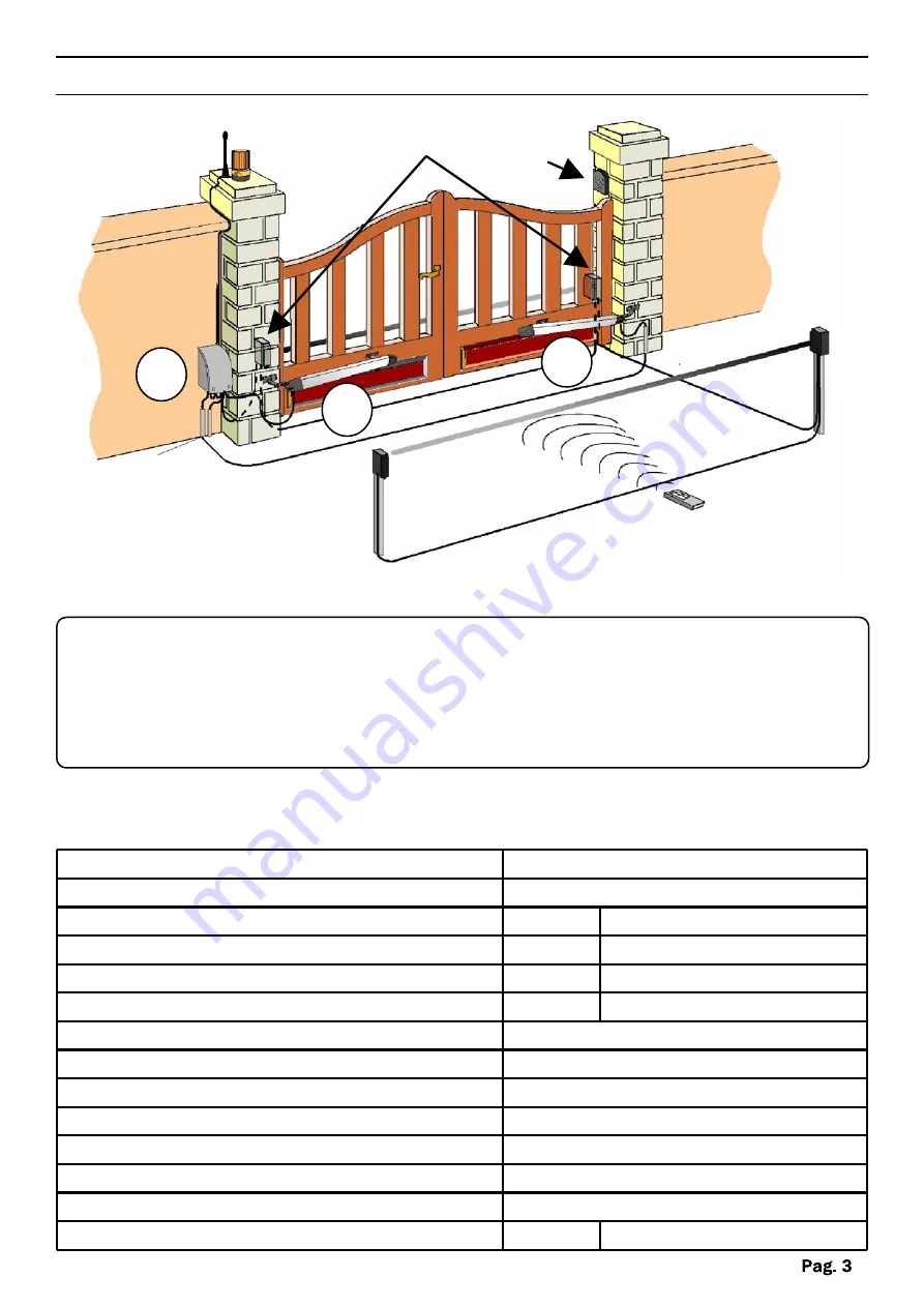
VIEW OF TYPICAL AUTOMATION AND NAMES OF COMPONENTS

4

3

1

1

5

6

7

8

Optimal installation

1- Operator

2- External photocell

3- Flashing warning light

4-  Antenna

5- Internal photocell

6- Electronic control unit

7- Key-switch

8- Remote control

TECHNICAL DATA

Summary of Contents for AMICO 400BZ

Page 1: ...installing thoroughly read this manual that is an integral part of the pack The CE mark conforms to European directive EEC 89 336 92 31 93 68 D L 04 12 1992 N 476 Our products if installed by qualified personnel capable to evaluate risks comply with norms UNI EN 12453 EN 12445 ...

Page 2: ...3 TECHNICAL DATA 3 DIMENSIONS 4 TYPICAL CONNECTION AND CABLE SECTION 4 CONSIDERATIONS FOR INSTALLATION 5 INSTALLATION 5 6 TROUBLESHOOTING 7 SAFETY PRECAUTIONS 8 PACKING CONTENTS 1 OPERATOR 1 KIT FASTENING PLATES AND RELATIVE ACCESSORIES 1 UNLOCKING KEY 1 CONDENSER 230Vca ...

Page 3: ...ng temperature 20 C 55 C weight 8 Kg Protection rating IP 55 Opening time 90 15 sec Rod stroke 400 mm Force of thrust 1500 N Motor current input 1 5 A 1 A 2 5 VIEW OF TYPICAL AUTOMATION AND NAMES OF COMPONENTS 4 3 1 1 5 6 7 8 Optimal installation 1 Operator 2 External photocell 3 Flashing warning light 4 Antenna 5 Internal photocell 6 Electronic control unit 7 Key switch 8 Remote control TECHNICAL...

Page 4: ...DIMENSIONS TYPICAL CONNECTION AND CABLE SECTION 2X1 5mm2 24 Vdc 4X1 5mm2 230 Vca 2X0 75mm2 4X0 75mm2 4X0 75mm2 2X0 75mm2 105 mm 825 mm 110 mm 400 mm 3X1 5mm2 230V Line RX Photocell TX Photocell ...

Page 5: ...ngs well on its hinges and is suitably lubricated It must also comply with the safety standards in force in the country of installation 1 Before fastening the brackets provided establish the coordinates using the data given in Table 1 bearing in mind that they are valid if the operator is at maximum extension minus one centimetre of the available stroke CD when the gate is closed to obtain maximum...

Page 6: ...S FIG 1 FIG 2 40mm A B Fix the back plate to the pillar FIG 1 Anchor the rear part of the piston to the plate and fasten it firmly FIG 2 1 Fit the anchor plate onto the piston fig 4 2 Close the gate 3 Move the piston with the plate already fitted towards the gate 4 Move the fitting to limit stop then move it back by approximately 1 cm and mark the position of the plate 5 realize the same operation...

Page 7: ...g or the beam is interrupted Check the connection remove any obstacle across the beam On giving a command with the remote control the gate doesn t open but works with the key command The remote control has not been memorised or the battery is flat Carry out the remote control learning procedure on the radio receiver or replace the battery with a new one The gate starts but stops immediately The fo...

Page 8: ...ntegrity safety and operation in the event incompatible devices and or components are installed Solely original spare parts should be used for repairs and replacements The installer must provide all the information relating to the operation maintenance and use of the individual parts components and system as a whole WARNINGS FOR THE USER Read the instructions and enclosed documentation carefully T...

Reviews: