background image


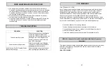
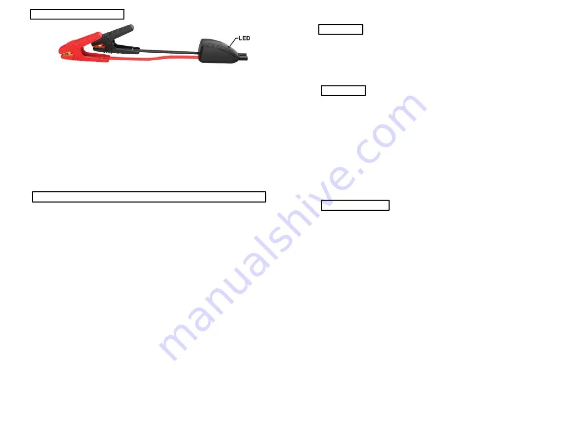
SMART ALLIGATOR CLIPS 


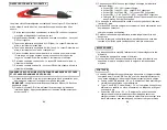
The smart alligator clips contain a single Amber/Green LED along with a warning 
buzzer for Faults and Error protection: 

1)  If connected correctly the LED on the smart alligator clips should turn 

green. 

1)  Standby Mode – Clips are not connected – The Green LED Flashes. 
2)  Vehicle battery voltage to LOW - Amber LED On, buzzer is beeping 
3)  Vehicle battery voltage to HIGH - Amber LED On, buzzer On solid. 
4)  Alligator clips connected to vehicle battery in reverse polarity. (Red clip to 

Black negative terminal, Black clip to Red positive terminal). Amber LED 
On, buzzer is beeping. 

5)  Short circuit protection - Amber LED On, buzzer is beeping. 
6)  Over heat protection – Amber LED is Flashing, buzzer is beeping. 

CHARGING THE VEHICLE JUMP STARTER & PORTABLE POWER BANK 
 

1)  Use the supplied micro USB cable to charge the Vehicle Jump Starter & 
Portable Power Bank.                                                                                

NOTE:

 While charging all of the other features and functions are NOT active. 

2)  There are four (4) blue LED’s that show the state of charge of the internal 

lithium battery. Simply press the touch button to activate these LED’s. 

3)  Each LED shows a percentage of charge of the internal lithium battery. 

a. 0% - 24% remaining LED 1 flashing. 
b. 25% - 49% LED 1 solid, LED 2 flashing. 
c. 50% - 74% LED 1 & 2 solid, LED 3 flashing. 
d. 75% - 99% LED 1, 2 & 3 solid, LED 4 flashing. 
e. 100% Charged, all of the LED’s are solid and will go into sleep mode 

after 10 seconds. 

4)  The battery level should be checked and charged every three (3) months. 
5)  DO NOT use any other charger to charge this Vehicle Jump Starter & 

Portable Power Bank. 

6)  Doing so can damage the internal battery and also be very dangerous.  
7)  When charging the internal battery, work in a well ventilated area and do 

not restrict ventilation in any way. 


10 


CAUTION 
 

1)  The device shall be stored indoors and protected from the elements. 
2)  The unit shall not be charged outdoors. 
3)  When in use, steps should be taken to reduce the exposure to rain, sleet, 

snow, and the like. 


USB PORTS 
 

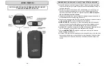
1)  There are three (3) USB ports contained in your Jump Starter & Portable 

Power Bank. Once your device is connected you must press the touch 
button to activate charging. 
a.  Standard USB Output port - 5VDC/2.4Amp. Used to charge your cell 

phone, tablet etc. 

b.  Type – C USB, In (Out) port – 5VDC/3Amp. This can power a tablet, 

power back, smart phone, camera etc.  

c.  Micro USB Input port – 5VDC/2A. This port is for charging your Jump 

Starter & Portable Power Bank. Only use the supplied cable to charge 
your Jump Starter & Portable Power Bank. 


LED FLASH LIGHTS 
 

1)  To turn the LED lights ON simply hold the Touch Button down for at least 

two (2) seconds.  

2)  To turn the LED lights OFF hold the Touch Button down for at least two (2) 

seconds. 


Summary of Contents for Battery Tender 030-1010-CA

Page 1: ...duct Failure to do so can result in serious injury Save this manual 392 0424 RA 2 CONTENTS Important Safety Instructions Warnings Product Specifications Product Overview Operating Instructions User Ma...

Page 2: ...ttery manufacture and manufacture of any equipment you intend to use in the vicinity of the battery Review all cautionary marking on these products and on engine 4 PERSONAL PRECAUTIONS 1 Consider havi...

Page 3: ...STARTER to severe physical shock 6 Do not attempt to modify the VEHICLE JUMP STARTER in any way 7 Do not place the VEHICLE JUMP STARTER in a microwave oven or pressurized container 8 Do not use the VE...

Page 4: ...the Jump Pack 4 Connect the RED positive clip to the positive post on the battery then the BLACK negative clip to the negative post on the battery 5 CAUTION Ensure the Vehicle Jump Pack and smart all...

Page 5: ...LED 1 2 solid LED 3 flashing d 75 99 LED 1 2 3 solid LED 4 flashing e 100 Charged all of the LED s are solid and will go into sleep mode after 10 seconds 4 The battery level should be checked and cha...

Page 6: ...ge Check the cable and connection and also try charging a different device 12 FCC WARNING Title 47 Subpart 15 105 b Note This equipment has been tested and found to comply with the limits for a class...

Page 7: ...ecommendations for safe and effective use 2 The product is disassembled or repaired by anyone who is not an authorized service representative of Battery Tender 3 The product was purchased from an unau...

Page 8: ...duire le risque d endommagement de la prise lectrique tirez sur la prise et non pas sur les cordons lors du d branchement du bloc d alimentation 7 N utilisez pas de bloc batterie ou d appareil endomma...

Page 9: ...la charge d une batterie interne travaillez dans une zone bien ventil e et ne limitez pas la ventilation d une mani re quelconque 2 Dans des conditions abusives du liquide pourrait tre ject de la batt...

Page 10: ...atterie ou bloc d alimentation 20 CARACT RISTIQUES DU PRODUIT Bloc d alimentation pour d marrage de secours et chargeur nomade de v hicules Port de sortie USB standard 5 V c c 2 4 amp res Type Port US...

Page 11: ...c d alimentation pour d marrage de secours 4 Connectez la pince positive ROUGE la borne positive sur la batterie puis la pince n gative NOIRE la borne n gative sur la batterie 5 MISE EN GARDE Assurez...

Page 12: ...a Voyant DEL 1 0 24 restant clignote b Voyant DEL 1 fixe 25 49 voyant DEL 2 clignotant c Voyant DEL 1 et 2 fixes 50 74 voyant DEL 3 clignotant d Voyant DEL 1 2 et 3 fixes 75 99 voyant DEL 4 clignotant...

Page 13: ...eur nomade de v hicules dans un environnement sec et temp rature ambiante si possible 3 Si vous voyez une bosse dans le bo tier ou si sentez une odeur chimique ARR TEZ imm diatement d utiliser le bloc...

Page 14: ...ence industriels scientifiques et m dicaux ISM Ce produit a t test selon les normes num r es et jug conforme au Code de l industrie Canada ES 001 et la proc dure de mesure selon la norme CISPR 11 CAN...

Reviews: