- 123 -
Latch Settings Menu
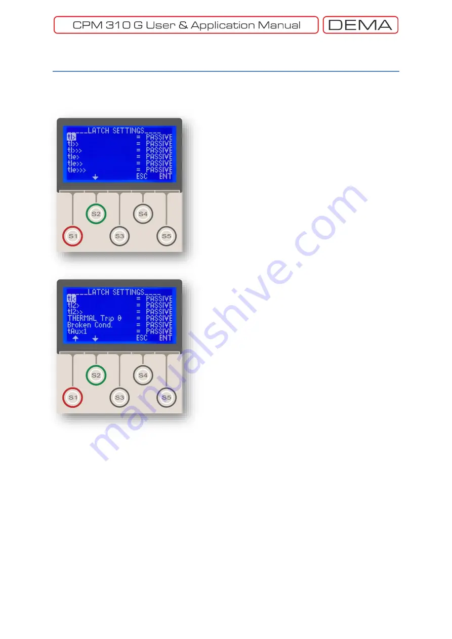
Latch Settings Menu contains the controls that
determine the latching behavior of functions and
programmable outputs.
By default, the protection and auxiliary timer functions
do not latch the Trip Relay or the other relays that they
are appointed to; similarly, programmable outputs do
not latch when activated by any functions. When a
function is needed to latch the Trip Relay, or the
programmable relays that they are appointed to; or a
programmable output relay is needed to be latched
regardless of the function that triggers it, the related
option on the Latch Settings Menu must be set as
Active
. As seen on the pictures on the left, all latch
options are set as
Passive
by default.
Functions that can latch Trip Relay, or the
programmable relays that they are appointed to, are
listed below:
tI>
Time delay trip due to phase overcurrent I>.
tI>>
Time delay trip due to phase overcurrent I>>.
tI>>>
Time delay trip due to phase overcurrent I>>>.
tI
e
>
Time delay trip due to earth overcurrent I
e
>.
tI
e
>>
Time delay trip due to earth overcurrent I
e
>>.
tI
e
>>>
Time delay trip due to earth overcurrent
I
e
>>>.
tI<
Time delay trip due to undercurrent I<.
tI
2
>
Time delay trip due to negative sequence I
2
>.
tI
2
>>
Time delay trip due to negative sequence I
2
>>.
Thermal Trip Θ
Trip due to thermal protection.
Broken Conductor
Trip due to broken conductor.
tAux1
Trip due to auxiliary timer no.1.
tAux2
Trip due to auxiliary timer no.2.
Buchholz Trip
Trip due to power transformer buchholz
signal.
Temperature Trip
Trip due to power transformer
temperature signal.
Pressure Trip
Trip due to power transformer pressure
signal.
Note that deleting the alarms on the Alarm Menu via
the DigiConnect PC program would also result in the
release of the latched relays.
↺
Main Screen » Menu »
Automatic Control Settings »
Latch Settings
Summary of Contents for CPM 310 G
Page 1: ...CPM 310 G Digital Overcurrent Protection Relay User Application Manual vEN 2016 03...
Page 2: ...2...
Page 6: ...6 ABOUT DEMA...
Page 11: ...11 INTRODUCTION...
Page 32: ...32 PACKING LABELING INFORMATION...
Page 34: ...34 OPERATING MANUAL...
Page 53: ...53 RELAY MENUS MANUAL...
Page 55: ...55 The Menu Tree...
Page 56: ...56...
Page 57: ...57...
Page 58: ...58...
Page 59: ...59...
Page 60: ...60...
Page 61: ...61...
Page 128: ...128 DIGICONNECT PC PROGRAM MANUAL...
Page 189: ...189 APPLICATION DIAGRAMS...
Page 191: ...191 Sample Power Transformer Protection Application Diagram...
Page 193: ...193 FUNDAMENTAL CABLING DIAGRAM...
Page 203: ...203 APPLICATION DIAGRAM NO 10 RS485 Cabling...
Page 204: ...204 TECHNICAL DATA...
Page 220: ...220 GLOSSARY...


