- 142 -
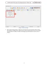
Measurements
»
Breaker Measurements
1.
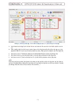
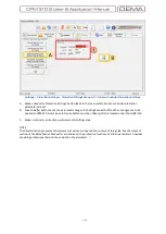
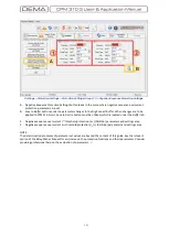
CB Measurements
window monitors and records all of the circuit breaker activity. The window displays:
Durations of the last closing and tripping operations, in seconds;
Total tripping numerator;
Cumulative total tripping current for each of R, S and T phases, in amperes (A);
Cumulative total tripping current-square for each of R, S and T phases, in amperes-square (A²).
Trip
and
Closing Time
values are of great importance for administrators to supervise the circuit breaker
mechanism condition. During evaluations, it must be kept in mind that the values shown are the measured
delays between the excitation of trip / closing release coils and loss / receive of signals from the normally
open auxiliary contact of the CB. Note that, assigning
52a
to any of the programmable inputs and cabling a
normally open auxiliary contact of the CB to that input is essential for the functionality of
Trip
and
Closing
Time
monitors.
Total Trips
,
Total A
and
Total A
2
measurements are the values that the administrator can use to evaluate
mechanical and electrical maintenance periods.
Total A
2
values are usually utilized for CBs with rated
voltage 36 kV or lower, while
Total A
values are evaluated for determination of maintenance periods of
CBs with rated voltage 52k V or higher. Documentation of the CB’s manufacturer must be examined to
decide whether to supervise
Total A
or
Total A²
values for a given CB.
□
Summary of Contents for CPM 310 G
Page 1: ...CPM 310 G Digital Overcurrent Protection Relay User Application Manual vEN 2016 03...
Page 2: ...2...
Page 6: ...6 ABOUT DEMA...
Page 11: ...11 INTRODUCTION...
Page 32: ...32 PACKING LABELING INFORMATION...
Page 34: ...34 OPERATING MANUAL...
Page 53: ...53 RELAY MENUS MANUAL...
Page 55: ...55 The Menu Tree...
Page 56: ...56...
Page 57: ...57...
Page 58: ...58...
Page 59: ...59...
Page 60: ...60...
Page 61: ...61...
Page 128: ...128 DIGICONNECT PC PROGRAM MANUAL...
Page 189: ...189 APPLICATION DIAGRAMS...
Page 191: ...191 Sample Power Transformer Protection Application Diagram...
Page 193: ...193 FUNDAMENTAL CABLING DIAGRAM...
Page 203: ...203 APPLICATION DIAGRAM NO 10 RS485 Cabling...
Page 204: ...204 TECHNICAL DATA...
Page 220: ...220 GLOSSARY...


