- 164 -
Settings
» Automatic Control Settings » CB Failure Settings
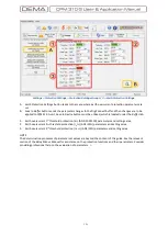
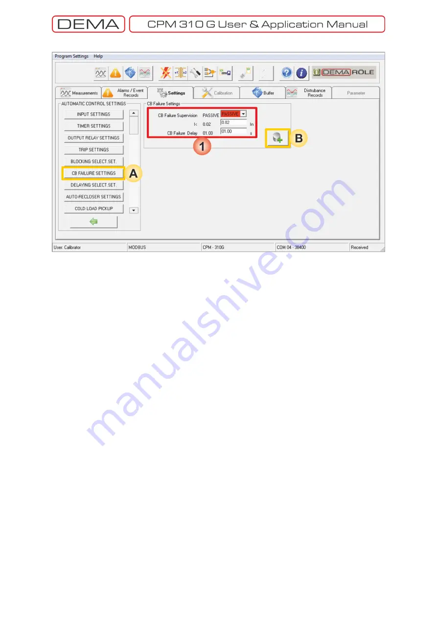
A.
CB Failure Settings
window is accessed by clicking the
CB Failure Settings
button in the
Automatic Control
Settings
window.
B.
Save to Buffer
button sends the parameter changes to the DigiConnect buffer. When changes are to be
applied to CPM 310 G unit,
Save to Device
button must be utilized, which is located under the
Buffer
tab.
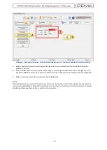
1.
CB Failure Settings
window comprises the control for having the CB protection function into or out of
service, as well as parameter setting fields.
CB Failure Supervision
This parameter can be set as Active or Passive to have the function into or out of service.
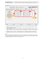
I<: CB Failure Threshold Current
I< is the upper limit of the circuit breaker pole current to decide that one or more poles of the circuit
breaker has failed to operate normally as the delay time expires. The function watches the
52a
(normally open auxiliary contact of the circuit breaker) input; once the 52a signal is lost, CB failure
delay time is counted until the pole current goes below the limit. If the current does not fall down
below the threshold value,
o
The function generates an alarm on the
Alarm Menu
and triggers the
Alarm LED
to inform the
user, and tells that a
Circuit Breaker Failure
condition is detected, or,
o
If applicable, triggers a dedicated output to start the configured alarming actions.
I< can be set as low as the current measurement lower limit, which is 0.02 I
n
, and is recommended to
be set to this value under normal conditions.
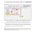
CB Failure Delay
CB failure delay time decides how long to wait before the measured current above the threshold value
is evaluated as a fault. Circuit breaker mechanical operation and arc extinguishing time values differ
for various brands and models, however, these values are below a certain value not exceeding 0.1s for
modern circuit breakers. Setting this value in the range of (0.05 – 0.1) s would be appropriate for most
of the applications. On the other hand, the set value may have to be determined beyond these values
for atypical cases.
It must be noted that, some requirements must be fulfilled for correct operation of this function;
A programmable input must be dedicated to this function with
CB Failure Protection
appointment, and
The dedicated input must be cabled to a normally open auxiliary contact of the circuit breaker.
□
Summary of Contents for CPM 310 G
Page 1: ...CPM 310 G Digital Overcurrent Protection Relay User Application Manual vEN 2016 03...
Page 2: ...2...
Page 6: ...6 ABOUT DEMA...
Page 11: ...11 INTRODUCTION...
Page 32: ...32 PACKING LABELING INFORMATION...
Page 34: ...34 OPERATING MANUAL...
Page 53: ...53 RELAY MENUS MANUAL...
Page 55: ...55 The Menu Tree...
Page 56: ...56...
Page 57: ...57...
Page 58: ...58...
Page 59: ...59...
Page 60: ...60...
Page 61: ...61...
Page 128: ...128 DIGICONNECT PC PROGRAM MANUAL...
Page 189: ...189 APPLICATION DIAGRAMS...
Page 191: ...191 Sample Power Transformer Protection Application Diagram...
Page 193: ...193 FUNDAMENTAL CABLING DIAGRAM...
Page 203: ...203 APPLICATION DIAGRAM NO 10 RS485 Cabling...
Page 204: ...204 TECHNICAL DATA...
Page 220: ...220 GLOSSARY...


