- 17 -
CPM 310 G: Internal & External Units
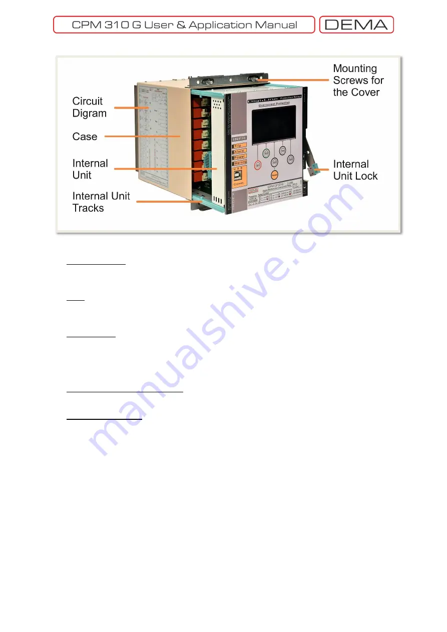
Circuit Diagram
CPM 310 G Circuit diagram is fixed on the relay case. Users do not need to keep documents for
basic cabling duties on the field thanks to this inerasable diagram.
Case
CPM 310 G case is made of special alloy inoxidant metal and coated with modern PVC coating techniques.
Male sockets belonging to terminals are located on the back of the case.
Internal Unit
The internal unit houses the entire electronic systems, making it possible to replace the whole unit within
seconds without having to black put the system. The modular design of electronic systems provides rapid
and affordable maintenance & reparation in need. Critical electronic components are screened from noises
in the Faraday cage inside of the unit.
Mounting Screws for the Cover
Mounting screws are fixed on the case and are employed to mount the cover on the case.
Internal Unit Tracks
High-endurance internal unit tracks provide robust draw-in and draw-out operation of the internal unit.
↺
Summary of Contents for CPM 310 G
Page 1: ...CPM 310 G Digital Overcurrent Protection Relay User Application Manual vEN 2016 03...
Page 2: ...2...
Page 6: ...6 ABOUT DEMA...
Page 11: ...11 INTRODUCTION...
Page 32: ...32 PACKING LABELING INFORMATION...
Page 34: ...34 OPERATING MANUAL...
Page 53: ...53 RELAY MENUS MANUAL...
Page 55: ...55 The Menu Tree...
Page 56: ...56...
Page 57: ...57...
Page 58: ...58...
Page 59: ...59...
Page 60: ...60...
Page 61: ...61...
Page 128: ...128 DIGICONNECT PC PROGRAM MANUAL...
Page 189: ...189 APPLICATION DIAGRAMS...
Page 191: ...191 Sample Power Transformer Protection Application Diagram...
Page 193: ...193 FUNDAMENTAL CABLING DIAGRAM...
Page 203: ...203 APPLICATION DIAGRAM NO 10 RS485 Cabling...
Page 204: ...204 TECHNICAL DATA...
Page 220: ...220 GLOSSARY...


