- 21 -
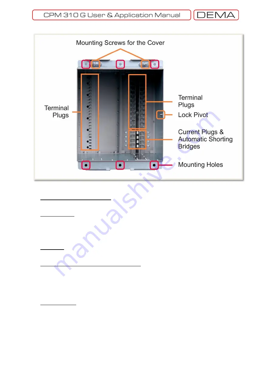
CPM 310 G: External Unit (Case) – Front View
Mounting Screws for the Cover
The cover is mounted onto the case via these screws. Screws are embedded and fixed on the case.
Terminal Plugs
Plugs make the electrical connection by locking to the sockets when the internal unit is drawn into the
case. Secondary current plugs are longer than the auxiliary plugs – this ensures the draw out of the internal
unit safe from unwanted circuit breaker commands induced by the transient signals occurring while the
sockets are disconnecting.
Lock Pivot
Internal unit locking mechanism locks to this pivot, providing mechanical and contacting stability.
Current Plugs & Automatic Shorting Bridges
Current plugs provide the electrical connection of the secondary circuit cabling to the internal unit circuits.
When the internal unit is drawn out, the automatic secondary current bridges safely short-circuits the
secondary terminals – by doing this, secondary circuit continuity is provided and open secondary circuit
cases are preventing. This feature enables operators to drive out the internal unit for replacement, testing
or similar purposes while the system is energized.
Mounting Holes
The relay case is mounted on the panel or rack from these mounting holes. Connection elements needed
for mounting the case is supplied within the product box.
□
Summary of Contents for CPM 310 G
Page 1: ...CPM 310 G Digital Overcurrent Protection Relay User Application Manual vEN 2016 03...
Page 2: ...2...
Page 6: ...6 ABOUT DEMA...
Page 11: ...11 INTRODUCTION...
Page 32: ...32 PACKING LABELING INFORMATION...
Page 34: ...34 OPERATING MANUAL...
Page 53: ...53 RELAY MENUS MANUAL...
Page 55: ...55 The Menu Tree...
Page 56: ...56...
Page 57: ...57...
Page 58: ...58...
Page 59: ...59...
Page 60: ...60...
Page 61: ...61...
Page 128: ...128 DIGICONNECT PC PROGRAM MANUAL...
Page 189: ...189 APPLICATION DIAGRAMS...
Page 191: ...191 Sample Power Transformer Protection Application Diagram...
Page 193: ...193 FUNDAMENTAL CABLING DIAGRAM...
Page 203: ...203 APPLICATION DIAGRAM NO 10 RS485 Cabling...
Page 204: ...204 TECHNICAL DATA...
Page 220: ...220 GLOSSARY...


